Question about installing new clutch/gear set in 1999 Bravo 3

BillWilliams

Petty Officer 3rd Class
Joined
May 23, 2021
Messages
76
My serial number is 0L440964.

I have service manual number 11.

I have determined I need gear set kit 43-883473A3. I counted the teeth on the gears and the main gears have 32 teeth and the pinion has 27.

I am also planning on ordering the bearing assembly 8M0103472. On mercruiserparts.com, it states if using on an older drive without a U joint shim, one must be used. Here's a link to the page: https://www.mercruiserparts.com/8m0103472-bearing-assy. It also talks about a new shimming procedure. Now, I did find on the mercury parts website that a shim is used on the newer Bravo drives. Is this something I need to worry about on mine? If so, how do I know which shim I need and does anyone have any information on the new procedure?

Thank you
 

BillWilliams

Petty Officer 3rd Class
Joined
May 23, 2021
Messages
76
I have found a post on another website stating the original timken race part number 28621 can be used with the new bearing assembly which removes the need for the shim. Does this sound right?

I also have found the superseded set part number 86763A2. Does anyone know if that set will work on the new pinion gear that will be in the gear set? My guess is it will not.
 

dubs283

Vice Admiral
Joined
Jul 27, 2005
Messages
5,322
I did find on the mercury parts website that a shim is used on the newer Bravo drives. Is this something I need to worry about on mine? If so, how do I know which shim I need and does anyone have any information on the new procedure?
Yes, a shim is required to properly install the updated gear set. The new gear set will come with instructions on how to properly install the updated gear/bearing set in the older style driveshaft housing

The shims take the place of the upper and lower thrust bearing races and are required for achieving the proper spacing of the gear set

Old style housings had numbers stamped into them regarding shim specs however the new style gear sets are a different dimension and require different shims/races.

There are a number of special tools required to properly install/measure the size of shims required for the new gear set. You may be spending twice as much to acquire the tools along with the updated gear/bearing set.
 

BillWilliams

Petty Officer 3rd Class
Joined
May 23, 2021
Messages
76
Thanks for the info but I don't think I did a good job of asking my question.

The 2001-17 bulletin does mention new thrust bearing shim races are required based on the thickness of the original shim races. The original shim races in my case are .091 thick and the bulletin indicates that I will need shim races that are .051 thick as replacements. So based on this, the upper and lower thrust bearing shim races are still needed (and assuming the bulletin is correct, I know what I need for that).

The shim to which I'm referring to in my previous post is mentioned for the new bearing assembly that is pressed onto the pinion gear. That's where my question is.
 

alldodge

Moderator
Staff member
Joined
Mar 8, 2009
Messages
42,056
Changing from old gear set to new gear set might need to look at Manual 28 and not 11.

Replacing clutch gear sets by manual 28 or using Bul 2001-17 the your now using manual 28 as I read it

Assemble drive gears and check preload as specified in 28, same goes for clutch
 

BillWilliams

Petty Officer 3rd Class
Joined
May 23, 2021
Messages
76
Thanks for the suggestion.

I do have service manual 28 as well in PDF form. I see there's a slight difference in the gear set assembly instructions as there does not appear to be a thrust race in the newer set. I think I'm good as far as the gear set goes.

I still have a concern when it comes to the bearing assembly that is pressed onto the pinion gear. Manual 28 is basically the same as 11 in those instructions but based on the website with the new bearing assembly, there is now a shim that needs to be installed and based on the mercury parts website, it goes on first before the smaller O.D. bearing.

I do have another question as well regarding setting the preload on the pinion gear assembly. I've used the old fashioned click torque wrenches and bar torque wrenches. The manual states using a torque wrench with a dial indicator. I've never used one with a dial indicator and was wondering if the other types can be used?
 

alldodge

Moderator
Staff member
Joined
Mar 8, 2009
Messages
42,056
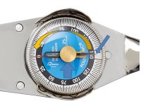
Must (really must) use a rolling torque meter to set preload. The dial has a pointer that is set to zero, then the wrench is turned several times and when stopped, look at pointer to see max torque it read.
 

BillWilliams

Petty Officer 3rd Class
Joined
May 23, 2021
Messages
76
Please forgive me if this is a stupid question, but is a rolling torque wrench a torque wrench with a dial indicator?
 

alldodge

Moderator
Staff member
Joined
Mar 8, 2009
Messages
42,056
No, its a torque wrench with a pointer. Before getting a reading, the thumb dial is turned so i aligns with the torque needle. In this pic counter clockwise. The pointer rest against the main dial needle.

Now turn wrench and max torque will move the thumb dial
The thumb dial is rotated depending on if CW or CCW torque is to be read

roll.jpg
 

BillWilliams

Petty Officer 3rd Class
Joined
May 23, 2021
Messages
76
Thanks. That is basically what the manual is saying to use then because it says use a torque wrench with a dial indicator on it.
 

BillWilliams

Petty Officer 3rd Class
Joined
May 23, 2021
Messages
76
Ok, I have another question (probably silly) regarding torque. When installing the u-joint assembly, the manual says 200 lb/ft. The thing that is throwing me is the chart used to calculate the torque setting. It shows the torque settings rising as the length of the torque wrench increases. That makes no sense to me since that is lengthening my lever. I have noticed the same chart values in manuals 11, 28 and 39 so I'm certain it's not a misprint.

As I read the chart, if my torque wrench is 24 inches in length, I would use a setting of 133 lb/ft on my wrench. With that 24 inches plus the 12 inches of the u-joint tool is a total of 36 inches and based on my calculations, that will give me 399 lb/ft of torque.

Obviously, I'm missing something. Can someone put my mind at ease?

Thanks
 

alldodge

Moderator
Staff member
Joined
Mar 8, 2009
Messages
42,056
No expert but my understanding is the TW is applying its torque the the square drive area. It measures at the square drive and is calibrated for the wrench flex. The longer the wrench the more flex, shorter less flex
 

04fxdwgi25

Chief Petty Officer
Joined
Mar 25, 2022
Messages
537
Are you talking about a "crows foot" adapter on the torque wrench instead of a socket? If so, then the calibration changes considerably, since there is a distance from the square hub and the center point of the bolt.

Just adding length to the TW handle changes nothing about the torque applied to the 1/2" hub the socket goes on, except the longer the handle, the easier it is to push (more leverage).
 

dubs283

Vice Admiral
Joined
Jul 27, 2005
Messages
5,322
Are you talking about a "crows foot" adapter on the torque wrench instead of a socket?
No, he's referencing the tool used to tighten the retaining ring for the input shaft bearing assy.

The torque wrench attaches to the end of the tool which is roughly 12" long, therfore the amount of torque applied to the retaining ring with the tool using a standard torque wrench does not match what you set the torque wrench to.

There is a chart in the manuals that designates what torque value to set the wrench to based on the length of the wrench you are using. It's confusing because the chart indicates the torque value you set the wrench to increases with torque wrench length.

Torque is a measure of rotational force. The wrench you use applies rotational force the the end of the 12" tool so that is where the wrench ends its use. The additional length of the tool causes the calculation to get a bit muddled because the rotational force applied with the wrench does not easily correlate to the lateral force on the end of the tool.

Trigonometry is required to calculate different torque values to determine set point based on wrench length. Mercury has done the math but the chart seems inverted because basic laws of physics teach us a longer lever equals less force required to achieve the same results, however its not lateral force we're measuring with a torque wrench, it's rotational force we need measured at the end of the wrench plus additional lateral force applied to the end of the tool to achieve a total of 200 lb/ft of rotational force to the opposite end of the tool. Not a simple/intuitive calculation
 

racerone

Supreme Mariner
Joined
Dec 28, 2013
Messages
37,818
Don't forget to use " mechanics blue " to check proper tooth contact !
 

tpenfield

Moderator
Staff member
Joined
Jul 18, 2011
Messages
18,040
Lately, in the few times that I have dis-assembled my Bravo 3 drives, I have marked the position of the castle nut (and the bearing carrier) relative to the housing, so that I can return them to their original 'tightness'.

It seems to work out OK. I was originally using a torque wrench, but the amount of torque that those things are spec'd at was a bit beyond what my wrench could reliably do. So, I was using a breaker bar and guest-imating the amount of torque I was placing based on the length of the tool/bar combined and the amount of force I was applying.

Having the marking of the original position seemed to be an additional factor to get the proper amount of torque. YMMV . . .
 

04fxdwgi25

Chief Petty Officer
Joined
Mar 25, 2022
Messages
537
No, he's referencing the tool used to tighten the retaining ring for the input shaft bearing assy.

The torque wrench attaches to the end of the tool which is roughly 12" long, therfore the amount of torque applied to the retaining ring with the tool using a standard torque wrench does not match what you set the torque wrench to.

There is a chart in the manuals that designates what torque value to set the wrench to based on the length of the wrench you are using. It's confusing because the chart indicates the torque value you set the wrench to increases with torque wrench length.

Torque is a measure of rotational force. The wrench you use applies rotational force the the end of the 12" tool so that is where the wrench ends its use. The additional length of the tool causes the calculation to get a bit muddled because the rotational force applied with the wrench does not easily correlate to the lateral force on the end of the tool.

Trigonometry is required to calculate different torque values to determine set point based on wrench length. Mercury has done the math but the chart seems inverted because basic laws of physics teach us a longer lever equals less force required to achieve the same results, however its not lateral force we're measuring with a torque wrench, it's rotational force we need measured at the end of the wrench plus additional lateral force applied to the end of the tool to achieve a total of 200 lb/ft of rotational force to the opposite end of the tool. Not a simple/intuitive calculation
OK, thanx. Same principal applies as to a crows foot. Recalculating the required torque needed to get the applied torque to the adapter.
 

BillWilliams

Petty Officer 3rd Class
Joined
May 23, 2021
Messages
76
tpenfield, I had a friend make the same suggestion but unfortunately, I had already disassembled things.
 
Top