Need to adjust the dial 1990 Force carbs mixture

gica

Chief Petty Officer
Joined
Feb 24, 2016
Messages
495
I want to take it to the lake this weekend and adjust the mixture and then the timing. I don't have the 90 book I do have the 92. So after adjusting all the components around the carbs, including timing at 28BTDC I have to adjust the carbs mixture and idle. Book says turn in all the way and turn out 1 full turn. Then 1/8 at a time out till runs rough mark, 1/8 in same way mark again and go in the middle. The thing is when I turn it in it goes almost to the end until it wants to die, I also read not to go in more than one turn. I think lean is in rich is out, not sure right now though. So I need some advice on this. Where do you guys have it. And also timing at 28BTDC is that ok? Thanks in advance.
 

The Force power

Commander
Joined
Feb 3, 2019
Messages
2,335
I want to take it to the lake this weekend and adjust the mixture and then the timing. I don't have the 90 book I do have the 92. So after adjusting all the components around the carbs, including timing at 28BTDC I have to adjust the carbs mixture and idle. Book says turn in all the way and turn out 1 full turn. Then 1/8 at a time out till runs rough mark, 1/8 in same way mark again and go in the middle. The thing is when I turn it in it goes almost to the end until it wants to die, I also read not to go in more than one turn. I think lean is in rich is out, not sure right now though. So I need some advice on this. Where do you guys have it. And also timing at 28BTDC is that ok? Thanks in advance.
In my experience..........I start at 11/8 from out & yes out = rich mixture / in = lean
MAKE SURE; all carbs have to be set the SAME
IN ADDITION;
7. Adjust idle speed to 700-750 RPM in the water in forward gear. Do this with the screw on the bottom of the timing tower. Loosen the locknut and adjust. Screwing in increases idle speed. Do this in small increments and let the engine rev and adjust itself before the next adjustment. A little goes a long way here. When correct, tighten the nut. Note that the scribed line on the roller will now be (usually) below the black roller a bit.
8. NOW we adjust the mixture on the carbs. Set all low speed needles to about 1 1/4 turns out from lightly seated. Do not force as this will damage either the needles or the seats.
8A. With the engine idling in neutral, turn each the needles in equally about 1/8 turn at a time. Give the engine a couple of seconds between each adjustment to stabilize. Adjust until the engine either "sags" or stalls. Note this setting.
8B. Now go the opposite direction. Adjust until the engine runs rough, burbles, or stalls. Note this setting.
8C. Set all needles to the average between the two settings: That is, for example, if it stalled at 3/4 turn out and burbled at 1 1/4 out then set all needles to 1 turn out.
8D. Readjust idle speed to 700-750 RPM.
9. Take the boat out on the water and do a "hole shot"--Full throttle acceleration from a stop. If the engine "sags" then recovers and picks-up it is too lean. Open the needles about 1/16 turn at a time until the engine accelerates with no hesitation.
If the engine sputters or coughs or burbles, then clears itself and accelerates, it is too rich. Close the needles about 1/16 turn at a time until the engine accelerates smoothly.

10. I can NOT stress this enough! NEVER set the low speed needles less that 1 turns out no matter how poor the idle or acceleration. To do so will run the engine too lean and detonation and melted pistons at or near full throttle operation will result.
 
Last edited:

gica

Chief Petty Officer
Joined
Feb 24, 2016
Messages
495
Yeah I have seen that before thanks. Last time I tried to set this I had the issue with the trigger wires on cyl 1 of one of the 2 engines so I could not do it right.
When I turned the screw out I did get the stalling but when I went the other way, I did not get the roughness until really close to the end. So, I was worried about it going too far towards lean(in) but I guess at idle it should not cause the knock. One thing is for sure I did not get roughness at 3/4 in. At least I did not notice it.
The other thing is the idle meter I am using is a timing gun and if I don't hold it against the #1 cable I get a fake reading if I press against it, it stabilizes. So I think I need 2 people. I was going to buy a tach meter to wrap around the coil wire to the spark plug to get a better reading.
Any suggestions?


topgun3690

Lieutenant Junior Grade
Joined
May 7, 2019
Messages
1,034
I just got one of these to verify my main tach was accurate.....so far it seems to work well.....the brand was Carbole (ebay) but looks exactly the same as the one in that link......1695352780073.png
 

gica

Chief Petty Officer
Joined
Feb 24, 2016
Messages
495

topgun3690

Lieutenant Junior Grade
Joined
May 7, 2019
Messages
1,034
I got the Carbole mainly because they claim it is waterproof...IP68 rating.....and a lifetime warranty. Funny thing is you cannot replace the battery, or turn it off, so if it quits working (dead battery) are they gonna send me a new one? Lol
 

gica

Chief Petty Officer
Joined
Feb 24, 2016
Messages
495
Wow that's stupid.
The only draw back that I rad about it in the reviews is the back light that is missing. Most are complaining about that. Didn't know about the battery.
 

jerryjerry05

Supreme Mariner
Joined
May 7, 2008
Messages
18,037
1990 WHAT???
The 3cyl. the carbs are set at 1 turn and left there. "Factory direction"
You might need to adjust them and 1/8th turn should be all you need.
The 125/120/150/50 all need to be set at 1 1/2 turn out then adjusted from there.
In the water. Warm motor and in gear, slowly turn the air screw in until it bucks, kicks or stutters then back out 1/2 turn.
FIRST, I'd do a starting fluid test on any motor then set carbs.
SF Test: motor running, spray SF around the intake side of the motor, that includes under the pack, coils and port cover ands carb bases. If that makes a difference in the way it runs then all the adjusting won't help nothing.
 

gica

Chief Petty Officer
Joined
Feb 24, 2016
Messages
495
1990 WHAT???
The 3cyl. the carbs are set at 1 turn and left there. "Factory direction"
You might need to adjust them and 1/8th turn should be all you need.
The 125/120/150/50 all need to be set at 1 1/2 turn out then adjusted from there.
In the water. Warm motor and in gear, slowly turn the air screw in until it bucks, kicks or stutters then back out 1/2 turn.
FIRST, I'd do a starting fluid test on any motor then set carbs.
SF Test: motor running, spray SF around the intake side of the motor, that includes under the pack, coils and port cover ands carb bases. If that makes a difference in the way it runs then all the adjusting won't help nothing.
Hey Jerry it's a 1990 Force 120hp.
One of the 2 motors was completely rebuilt lower drive too
The timing I set at 28BTDC is that ok?
 
Last edited:

gica

Chief Petty Officer
Joined
Feb 24, 2016
Messages
495
1990 WHAT???
The 3cyl. the carbs are set at 1 turn and left there. "Factory direction"
You might need to adjust them and 1/8th turn should be all you need.
The 125/120/150/50 all need to be set at 1 1/2 turn out then adjusted from there.
In the water. Warm motor and in gear, slowly turn the air screw in until it bucks, kicks or stutters then back out 1/2 turn.
FIRST, I'd do a starting fluid test on any motor then set carbs.
SF Test: motor running, spray SF around the intake side of the motor, that includes under the pack, coils and port cover ands carb bases. If that makes a difference in the way it runs then all the adjusting won't help nothing.
Ok I just read the post again and noticed the adjustment is done in gear. I have not done that before. At idle when I turned the screw in I got almost to the end before noticing any stalling. But in gear it should be more obvious.
I assume the 1 1/2 out and dialing it in to the stall position in gear and back out half a turn still applies? Thanks
 

gica

Chief Petty Officer
Joined
Feb 24, 2016
Messages
495
I took the boat to the lake and it wasn't pretty. I managed to adjust one of the engines idle and everything. The second one would not hold idle in gear.
I have to mention I removed the kill switches on both on was not working at all.
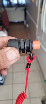
I bought 2 new ones and want to make sure I put them on right.
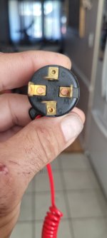
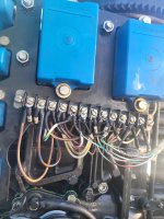
In tye picture you'll see 4 connectors the M has continuity when the lanyard is attached. I have no clue what the right way is. All I know is without the switches I get ground at the engine on one motor and nothing on the other.
I drove the boat at higher speed and the motors were better together my rom went to 4200 at wot could be more I did not adjust the tachs. But as soon as I would put it in neutral bot engines died. Would have to start and imediatley go in gear. It was a pain.
Let me know please on the lenyards. I have to reopen and clean the carbs. The filters were full of sand before I changed them and one might have leaked. I will also have to repairthe trigger wires as 2 were broken for number one and I repaired them already. Thanks
 

Attachments

  • 20230925_104316.jpg
    20230925_104316.jpg
    861.1 KB · Views: 0
  • 20230925_104305.jpg
    20230925_104305.jpg
    857.2 KB · Views: 0

Nordin

Commander
Joined
Jun 12, 2010
Messages
2,555
Lanyard should have open circuit when attached.
When removed there should be a short circuit at lanyard.
To stop the engine you ground out the black/yellow (stop wire) wire.
 

gica

Chief Petty Officer
Joined
Feb 24, 2016
Messages
495
Lanyard should have open circuit when attached.
When removed there should be a short circuit at lanyard.
To stop the engine you ground out the black/yellow (stop wire) wire.
Ok so the M in the picture has continuity with laynard attached. I should use the other 2 connectors right. Also I have ground without these kill switches connected so black and white wire at the dash disconnected. I have to check why I get ground and why the engine starts. The other engine also starts and stops with ignition and no kill attached and no ground at the purple or white wire at the junction. F..k
 

The Force power

Commander
Joined
Feb 3, 2019
Messages
2,335
Ok so the M in the picture has continuity with laynard attached. I should use the other 2 connectors right.
YES
Also I have ground without these kill switches connected so black and white wire at the dash disconnected. I have to check why I get ground and why the engine starts.
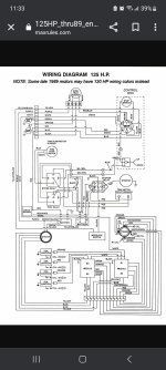
Check per schematic you got in your other post
The other engine also starts and stops with ignition and no kill attached and no ground at the purple or white wire at the junction.
So that good
 

gica

Chief Petty Officer
Joined
Feb 24, 2016
Messages
495
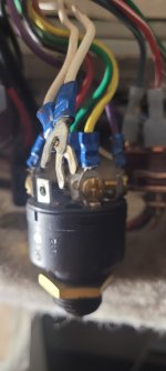
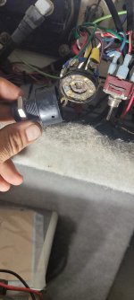
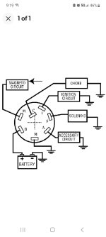
Ok so the white wire that has the ground which goes to the junction box and connects to 2 black/yellows was connected to the ignition switch M see 1st picture. I am including the ignition switch diagram I wrote picture 2.
The other ignition switch fell apart when I touched it so I have to replace it. That one also had the 2 white wires connected to M on the switch but somehow they were not grounded at the switch. I am trying to figure out why M has ground or if that is ok why the white wires are connected there. It is like a bypass to always have ground. So the 2 white wires for each switch are one from the kill switch and the other to the engine at the junction near the starter connecting to the 2 black/ yellows.
The ignition switch that is still good is like in the picture and the 2 M connectors are shorted or there is continuity between them. That's why I had ground at one engine white wire even though the kill switch was not connected. I don't know why that engine even started but it did and ran great.
So I am looking for an ignition switch now..
 

Attachments

  • 20230925_210254.jpg
    20230925_210254.jpg
    845.3 KB · Views: 1
  • 20230925_210306.jpg
    20230925_210306.jpg
    849.4 KB · Views: 1
  • 16957012504922937479006311878236.jpg
    16957012504922937479006311878236.jpg
    1.1 MB · Views: 2
  • Screenshot_20230925_211903_eBay.jpg
    Screenshot_20230925_211903_eBay.jpg
    200.9 KB · Views: 1
Last edited:

gica

Chief Petty Officer
Joined
Feb 24, 2016
Messages
495
This is a diagram that I found it looks pretty close to my ignition except the blue wire that goes to M is black on mine.
 

Attachments

  • Screenshot_20230925_233345_Chrome.jpg
    Screenshot_20230925_233345_Chrome.jpg
    610 KB · Views: 4

The Force power

Commander
Joined
Feb 3, 2019
Messages
2,335
This is a diagram that I found it looks pretty close to my ignition except the blue wire that goes to M is black on mine.
Check where/what your black wire goes/does, to verify if your black is functioning as blue would
 

gica

Chief Petty Officer
Joined
Feb 24, 2016
Messages
495
I just found out thatvone 9f tye engines thatbI thought was adjusted and was ready to go had the idle adjustment bolt come loose and that's why it wasn't holding idle. I forgot to lock it up with the nut. Oh well at least thatbone is good. Working on the trigger wiring repairs on the other one. Also the kill switches are coming today so I will have to see the issue with tye grounded one. In the diagram above it shows both whites going to one of the M connectors. But thei are supposed to get their ground from the kill switch black to the white not from the ignition switch
 

gica

Chief Petty Officer
Joined
Feb 24, 2016
Messages
495
Ok got the new ignition switches and I tested them with a meter. So when the key is off there is continuity between the two M connectors on the switch. As soon as you turn the key the circuit opens and the kill switch becomes the one that controls the
continuity. So I have to check if the switch I still have on operates that way. It might not open the connection between the 2 M connectors. So that's how the kill switch operates. That's why you turn off the motor from the switch even if the kill switches are not on and the engine runs. The white wire gets ground and shut's off the engine. And probably the power gets disconnected also. At least I think that's how it works. Now I should have no ground to the wire at the engine with the key on.
I also fixed every small wire at the junction where the trigger wires go. I did find at least 3 that were either broken or broke off right away. Most were ok but I redid them anyways.
I will clean the carbs again since I had the sandy broken filter issue before changing it. That filter was either old or there is stuff in the tank. They both look super clean now. If I clean them again I hope I can get idle this time around. It's long overdue.
 

Attachments

  • IMG_20230926_122545_01.jpg
    IMG_20230926_122545_01.jpg
    1.4 MB · Views: 0
Top