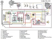
I'm not sure that the carb'd version uses the est.. let me see what I can find.After looking at the schematic I think we now need one for the carbed version to see how the Delco EST is wired to the engine harness....
That's kind of what I was thinking.. then I could retain the oem filter and keep a nice clean factory lookAs long as the pressure is right for a carb and it’s wired with the safety switch it should work
Disregard my question about moving the distributor- found the bolt that loosens the base to allow the distributor to moveI found this in another thread- I still don't understand how to adjust timing with this distributor since it doesn't appear to move at all....
Good News!
Ok, for anyone who is contemplating this swap, the VP Gi engine has the Delco EST distributor like the Voyager sold in kits around the web. I verified this by pulling up both distributors for the GL and Gi 5.0 VPs. The GL engines have a mechanical spark advance. The Gi engines have a reluctor, coil, and module. The module is VP p/n 3854003, which crosses to Delco D1965A and GM 10482830 or Sierra 18-5107-1. This is the marine module, and is different from the car module. The car module has a small advance curve as a limp mode, and will need to be hooked up to an ECM to calculate total spark advance. The marine modules have a total advance of 20degrees, in a straight linear progression that is all in by 3000 rpm. This means that if you have a TBI GM based engine, and you want to swap to a carburetor, all you need to do is pull the 4 wire plug from the ECM and cover the hole. You will need the shunt to set base timing.
I did a search for the GM 10482830 module, and found the advance curve etc. I also read about people who had been sold one of the $500 Voyager kits while converting a TBI engine to carburetor. They figured out later that they already had this ignition which the company who sold it to them also knew..........
So, the distributor that is on the engine will be getting some love and new parts so that there are spares on the boat in case of trouble.
Cheers,
Doug
I like how you think- i'm very happy to be back in control of how my boat runs! I didn't like being at the mercy of outdated hardware/software! My low pressure pump runs at 10 psi and the edelbrock carb I got says not to go over 6.5.. So I have a regulator coming that should let be get my pressure down to that.And back to the fuel pump, maybe look up the specs for the OEM Volvo low pressure pump, it may already be at the right pressure for the job.
Once you switch over to a carb and learn how to rebuild them and realize that Holley, Edelbrock and yes even Quadrajet parts are easy to find, you will be glad to be free of planned obsolescence (NLA parts) fuel injection. It is because of the collector car and muscle car market that carb parts can be found for old models easier than EFI.
So after giving myself a headache pouring over the wiring diagrams, I thought it would make sense to compare the Gi wiring diagram to the GL diagram. There's actually not many differences, and if worst comes to worst I think you could add in the wiring if necessary to make it work, although I may not even have to. I have a few questions to follow- i'm just not sure which way the power "flows" through the wiring harness- some essential components that I wired directly on the GL run through the Mefi on the Gi- hopefully I can make sense in what I am saying.. Pics to followLayout 1 (marinepowerusa.com)
page 17, you don't need the shift assist/interrupt stuff because Volvo doesn't use that AFAIK
purple and grey wire are the ones you would need to figure out how to hook up. Look at the wiring diagram, find those in the engine wiring harness.
take a look at this, this shows how the Delco EST connects to the ignition system, you may have to add some wiring to make it work....
also search these forums, there are a number of threads on this....
Good news! I was able to trace the circuit for the ignition coil, and it looks like I won't have to do ANYthing for it to work normally. If you look at relay 14, pin 87 powers the pink/white wire. When I ohmed the pink/white wire with the purple wire off the ignition harness, voila resistance! So it looks like the red/purple wire I was concerned about is a non issue as everything that needs to happen powerwise happens before this red/purple wire reaches the ECM. This pink/white wire gets power when keyed on and powers the purple ignition wire as far as I can tell. And I can't see how the ECM could interrupt the signal in any way..Ok find the purple wire connection on the ignition switch (terminals will have a red wire which is battery voltage, purple which gets voltage when when you turn the ignition to ON, and the yellow/red wire which gets voltage when you turn the switch to start). Then follow that wire in the harness and see where it ends. You need to connect with that..
Actually yes! I'm hoping to have her running by tonight.. found the perfect regulator (I think).. I will post up a parts list once I know if its gonna workAny more luck? John (BoatsUnlimited) is not finding anything wrong with my mefi. He ran it for over an hour and even heated it to 140 degrees and nothing. I am so tired of chasing this I may switch as well. Stop spending good money after bad? I was hoping to use the new fuel pump I just bought. that was a lot of money on that stupid thing! Maybe I can get a regulator that has a return on it? anyway just wonder how the progress is on the project?