LiFePO Batteries ???

tpenfield

Moderator
Staff member
Joined
Jul 18, 2011
Messages
18,039
You spelled phuck'n wrong....
Back in the day . . .when I was in college working summers at an electronics company that made/sold A/D and D/A converters . . . we used to write "NFG" on the parts that failed final test.

One of the managers questioned our use of profanity, and we said . . . it means "Not Functioning Good" :ROFLMAO:
 

tpenfield

Moderator
Staff member
Joined
Jul 18, 2011
Messages
18,039
Was the alternator working before you started this project?
I am not sure. I was having some charging trouble last year, but I never diagnosed it.

During my initial testing, the starboard alternator voltage fluctuated (over voltage, then under voltage) and created a bunch of warnings in the VesselView. After I shut the engine down and cleared the voltage faults, the alternator was not charging. I just tested it yesterday . . . still not charging.

The port engine is charging and the voltage while running is in a proper range (14.6 volts).
 

tpenfield

Moderator
Staff member
Joined
Jul 18, 2011
Messages
18,039
Quick update . . .

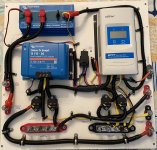
I took the 'off-grid' panel out of the boat and did the re-wiring as planned.
.
IMG_6150.JPG
.
So . . . the DC-DC charger will be activated when the port engine ignition is on. The port engine used to be in charge of charging the inverter bank, now it is in charge of charging the LiFePO4 (House) bank.

I also corrected some wiring issues that I found with the FET isolator.

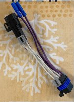
In order to tap into the key switch ignition feed (proverbial 'purple' wire) I made an extension cable for the port key switch. It uses Delphi Metri-pack connectors (6-pin).
.
IMG_6151.JPG
.
So this cable has the tap into both the Purple and the Purple/White wires. Using an extension cable allows me to keep the original cabling un-touched.

I will hook everything up tomorrow and give it a test.
 

tpenfield

Moderator
Staff member
Joined
Jul 18, 2011
Messages
18,039
OMG . . . it's working !!! :D

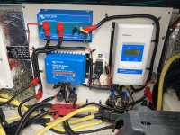
I re-installed the off-grid panel and got it all wired up. Installed my cable splice thingy on the port engine key switch and gave it a test.

IMG_6160.JPG
.
IMG_6159.PNG
.
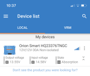
The charger was in bulk mode for a while, then shifted to absorption mode. In bulk mode, the alternator was dragged down by about 1 volt (13.6 instead of 14.6), but absorption mode is back up to 14.6 volts.
.
IMG_6162.PNG
.
IMG_6161.PNG
.
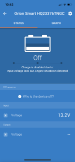
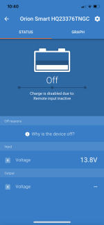
Engine shutdown detection is working as well as the key switch input, so it won't charge in case the ignition switch gets left on and engine not running.

One thing I'll need to get a handle is current draw while the device is inactive (off). It seems to have bluetooth when the charger is connected yet charging is 'off'. :unsure:
.
 

bruceb58

Supreme Mariner
Joined
Mar 5, 2006
Messages
30,537
Engine shutdown detection is working as well as the key switch input, so it won't charge in case the ignition switch gets left on and engine not running.
The engine detection will always keep that from happening. Like I said, you don't need to wire in the ignition feed at all!

Standby current is 1 mA. You don't need to worry about it.
 

tpenfield

Moderator
Staff member
Joined
Jul 18, 2011
Messages
18,039
An interesting thing happened this morning as I was running the engines to purge some de-scaler solution (an annual ritual for many of us salt water folks).

The starboard alternator started putting out voltage. It happened when I rev'ed the engine up to around 800-1,000 RPM . . . it basically did an over voltage like before (15.5-16 volts).:unsure: The Smartcraft system got all pissed-off and set a constant alarm off . . . the VesselView had a bunch of faults, etc. Had to clean up the 'mess' with the Diacom software.

Anyway . . . I should have a new alternator on Thursday. Hopefully that solves the issue.

A nice thing about the set-up with the 2 alt/2 battery isolator is that even though I have the DC-DC charger on the port engine/battery/key-switch, the charging can come from both engines, as needed.

In other news . . . I realized that the disgusting-looking electrical box on the starboard side has gotten that way because water is getting in there and does not seem to be draining very well.:oops: Add that to the fix-it list.:rolleyes:
 

Scott Danforth

Grumpy Vintage Moderator still playing with boats
Staff member
Joined
Jul 23, 2011
Messages
49,534
sounds like you have a lazy regulator on the starboard alternator.
 

tpenfield

Moderator
Staff member
Joined
Jul 18, 2011
Messages
18,039
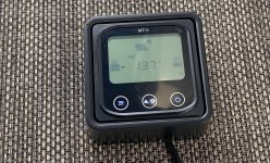
I've only had the system up and running for 1 day and I am already tired of opening the engine hatch to look at the solar charging status.

So, I ordered the remote panel for the EPEver.
 

tpenfield

Moderator
Staff member
Joined
Jul 18, 2011
Messages
18,039
Quick Update . . .

The ArgoFET isolator is being the source of some frustrations . . . essentially the solar system is overcharging the starter batteries and I believe the FET isolator is the source of the issue. The documentation on the innerds of the ArgoFET is very light, but possibly it is an N-channel FET and the 'activation' input is applying power to the 'gate' of the FET. I checked the activation current during operation and it was about 175 ma in decent solar conditions . . . more in the 50 ma range in lower sun light.

I'm using the solar input to activate the FET, but I think I need to create a voltage drop along the activation circuit, so it is lower than the output range of the starter battery feed from the solar controller (EPEver unit).

I am testing a 25 ohm resistor in series to see if that works out in creating the right amount of voltage drop.

Here is a video of the EPEver status

 
Last edited:

tpenfield

Moderator
Staff member
Joined
Jul 18, 2011
Messages
18,039
I got the remote monitor today . . . hooked it up. Just got to find a place to install it.
IMG_6194.JPG
.
In other news, I have figured out that the starter batteries were charging via the voltage from the FET isolator 'activation' feed. I've experimented with a few resistors to get a voltage drop. 220 Ohms is working out OK, but I have ordered a few Zener diodes to enhance the circuitry.
 

tpenfield

Moderator
Staff member
Joined
Jul 18, 2011
Messages
18,039
Update . . .

Still messing with the Victron ArgoFET isolator . . . It looks like the activation voltage/current is what is charging/maintaining the starter batteries. As such, it is over charging them. The internal aspects of the ArgoFET are a bit of a mystery, as it is not well documented on the Victron website.

On a do-over, I'd probably go with an ACR instead of the isolator. The problem with the FET isolator is that it needs to be activated in order for the EPEver to 'see' it. Therefore, the activation voltage becomes part of the mix. I am getting the activation voltage from the solar panel, which has its plusses and minuses . . . the '+' being that it turns itself off at night. The '-' is that I need to regulate the voltage better.

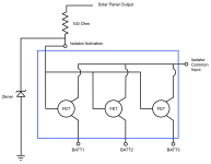
I'm working on a solution to regulate the activation voltage to be more in the range of the batteries. My sketch of the ArgoFET plus a few external components . . .
.
ARGOFET-Schematic-1.png
.
I have ordered a few 5 watt Zener diodes (12v, 14v, 15v) and a bunch of 5 watt resistors to see what works the best. Sort of engineering on-the-fly. 🤪
 

tpenfield

Moderator
Staff member
Joined
Jul 18, 2011
Messages
18,039
All Set . . . (I hope)

I added a 100 Ohm resistor and a 14 volt Zener diode to the FET activation circuit to regulate the activation voltage. It seems to be working as intended.

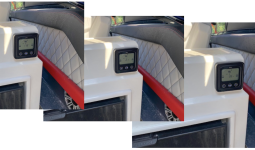
I installed the remote display panel for the EPEver. It is mounted to the wet bar, as that was about the 'best' place for it. No room at/near the helm.

Here is the display with the panel readings (getting late in the day).
17.8 volts, 2.1 amps, 36 watts . . .

The most wattage that I have seen from the panel is 57 watts, which is probably fine, but if I re-do the soft top of the radar arch, I may go with a better solar panel.
.
MT-11-Installation.png
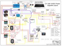
Here is the final schematic . . .
.
CY-338-Power-Diagram-LiFePO4-4D3.jpg
.
I'll be watching the charging over the next few days.

On to the Outdrive repairs . . . :rolleyes:
 

alldodge

Moderator
Staff member
Joined
Mar 8, 2009
Messages
42,054
Question
A Bat charger reduces the amount of Amps as the need for charge is decreased. The solar charger outputs X amount and is dependent on the sun. What regulates the excess power not needed, and where does it go?
 
Top