Kill switch replacement

AlThePal78

Cadet
Joined
Jul 27, 2023
Messages
12
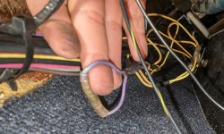
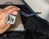
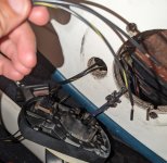
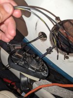
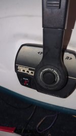
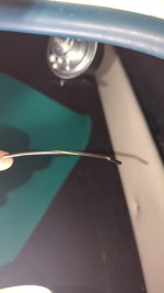
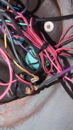
So the kill switch I'm replacing. I'm trying to figure out where would I put the actual black and yellow wire cuz I do not see another one with the other boat wires? Additionally, the original kill switch was purple wires with a purple and white wire as well.
 

Attachments

  • PXL_20230728_013054682~2.jpg
    PXL_20230728_013054682~2.jpg
    697.3 KB · Views: 3
  • PXL_20230728_005346769~2.jpg
    PXL_20230728_005346769~2.jpg
    681.9 KB · Views: 3
  • PXL_20230728_005401805~2.jpg
    PXL_20230728_005401805~2.jpg
    1.4 MB · Views: 3
  • PXL_20230728_005401805.jpg
    PXL_20230728_005401805.jpg
    2.3 MB · Views: 3

brodmann

Chief Petty Officer
Joined
Jun 17, 2008
Messages
426
There should only be two wires. Are you replacing the lanyard switch? All that switch does in ground the ignition system. Again there should only be 2 wires and it makes no difference which one goes where. All that does is make a connection if the clip is pulled out. What are you replacing exactly, and what are you replacing it with?
 

AlThePal78

Cadet
Joined
Jul 27, 2023
Messages
12
Yes I am replacing the lanyard switch. I don't know where the second wire connects too. Is it the yellow red one or purple one? That is all I need to accomplish because it is back on
 

Attachments

  • 16905157943587130023626611977935.jpg
    16905157943587130023626611977935.jpg
    773.8 KB · Views: 2
  • 16905158193868768395037342984876.jpg
    16905158193868768395037342984876.jpg
    440 KB · Views: 2

AlThePal78

Cadet
Joined
Jul 27, 2023
Messages
12
There should only be two wires. Are you replacing the lanyard switch? All that switch does in ground the ignition system. Again there should only be 2 wires and it makes no difference which one goes where. All that does is make a connection if the clip is pulled out. What are you replacing exactly, and what are you replacing it with?
There is no black and yellow wire indignation switch here so I didn't know where to connect the second switch
 

Attachments

  • 16905160860708581518800748330647.jpg
    16905160860708581518800748330647.jpg
    1.1 MB · Views: 2

04fxdwgi25

Chief Petty Officer
Joined
Mar 25, 2022
Messages
537
Probably can start by indicating what propulsion system you have.

Different between the outboard and sterndrive.

PS: That ignition switch has been bubba'd. Suggest installing proper sealed ring terminals on the wires and reterminate
 

04fxdwgi25

Chief Petty Officer
Joined
Mar 25, 2022
Messages
537
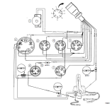
For the I/O system. Yellow / red are for the starter neutral safety switch. Purples are for the kill switch.
1690525640392.png
 

Scott Danforth

Grumpy Vintage Moderator still playing with boats
Staff member
Joined
Jul 23, 2011
Messages
49,545
there are two types of kill switches. Three if you count the combo switch

those that are normally open and held closed with the lanyard. these are for I/O's and powered ignition. when you pull the lanyard, it breaks the connection. these are normally in the purple wire

there are also the normally closed and held open with the lanyard. these are for magneto ignitions on outboards. these tie between black (ground) and yellow from the magneto. this shorts the ignition to ground thus killing the outboard

and there are the combo switches with two connections. depending on application you only need one.

based on your first post

So the kill switch I'm replacing. I'm trying to figure out where would I put the actual black and yellow wire cuz I do not see another one with the other boat wires? Additionally, the original kill switch was purple wires with a purple and white wire as well.
you have a switch for an outboard and based on the wiring, it looks like you have an I/O
 

AlThePal78

Cadet
Joined
Jul 27, 2023
Messages
12
there are two types of kill switches. Three if you count the combo switch

those that are normally open and held closed with the lanyard. these are for I/O's and powered ignition. when you pull the lanyard, it breaks the connection. these are normally in the purple wire

there are also the normally closed and held open with the lanyard. these are for magneto ignitions on outboards. these tie between black (ground) and yellow from the magneto. this shorts the ignition to ground thus killing the outboard

and there are the combo switches with two connections. depending on application you only need one.

based on your first post


you have a switch for an outboard and based on the wiring, it looks like you have an I/O
Yes it's I/o
 

AlThePal78

Cadet
Joined
Jul 27, 2023
Messages
12
So I have an inboard/outboard or stern drive, it is a sea ray 180 bowrider. I can't find the second purple wire that related to the kill switch. I bought the run/off switch but it was the black ground and the black and yellow. I thought it would do the same thing. I now need to replace a bunk on my trailer the bunk must be old. I don't have anyone that can drive my boat long enough so I can replace it myself. So now I am on two different problems.. I need to buy the proper kill switch and then I have to find the second purple wire. Then I have to repair the bunk. More then likely I will have to replace them both.
 

04fxdwgi25

Chief Petty Officer
Joined
Mar 25, 2022
Messages
537
Ones with the black wires are for the outboards.

As shown in the diagram, the purple feeds the ignition, with the lanyard switch in series in the circuit. In your 1st picture, you show a purple wire with a connection on it. Break that connection and install the safety switch in between the 2 wire ends.

To test and prove the switch out: Put an ohm meter across the switch leads and trip the safety lanyard. If the meter goes from closed to open, it will work for I/O's to open the ignition circuit. If the switch goes from open to closed, it is for the outboards to ground out the magneto.
 
Last edited:

AlThePal78

Cadet
Joined
Jul 27, 2023
Messages
12
Ones with the black wires are for the outboards.

As shown in the diagram, the purple feeds the ignition, with the lanyard switch in series in the circuit. In your 1st picture, you show a purple wire with a connection on it. Break that connection and install the safety switch in between the 2 wire ends.

To test and prove the switch out: Put an ohm .
So you are saying, that purple wire, needs to be cut and spliced, then in one side put it through one side of the purple wire to the switch , then the other side if I had the proper switch okay I get it now
 

Scott Danforth

Grumpy Vintage Moderator still playing with boats
Staff member
Joined
Jul 23, 2011
Messages
49,545
It's one purple wire. The connector shown in your first picture. Disconnect that connection and put the switch in between the two connectors

Use a hydraulic jack, some jack stands and some pieces of 2x6 to lift the boat off the one bunk to replace it
 

AlThePal78

Cadet
Joined
Jul 27, 2023
Messages
12
It's one purple wire. The connector shown in your first picture. Disconnect that connection and put the switch in between the two connectors

Use a hydraulic jack, some jack stands and some pieces of 2x6 to lift the boat off the one bunk to replace it
I'm going to need help with lifting the boat I don't own any of that equipment to do so.
 
Top