Hydrolocked in the parkinglot

gica

Chief Petty Officer
Joined
Feb 24, 2016
Messages
495
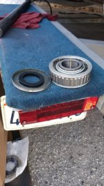
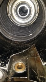
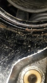
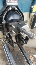
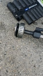
So I initially used a slide hammer to get the bearing out and it failed to do so so I ordered the proper tool and finally got it out.
20210214_141541.jpg20210214_141643.jpg20210214_151830.jpg
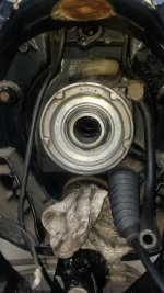
My question now is since the oil seal came out also when I put it back is it pushed all the way against the back of the designated space right? See picture
20210214_152504.jpg
Also I took out the trim switches one was really dry outside(port) the other had grease all over and also broke up in pieces. When I put the wires back does it have a positive and a negative or it doesn't matter?
20210214_152650.jpg
 

Grub54891

Admiral
Joined
Jun 17, 2012
Messages
6,079
So I initially used a slide hammer to get the bearing out and it failed to do so so I ordered the proper tool and finally got it out.
View attachment 333869View attachment 333870View attachment 333871
My question now is since the oil seal came out also when I put it back is it pushed all the way against the back of the designated space right? See picture
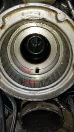
View attachment 333872
Also I took out the trim switches one was really dry outside(port) the other had grease all over and also broke up in pieces. When I put the wires back does it have a positive and a negative or it doesn't matter?
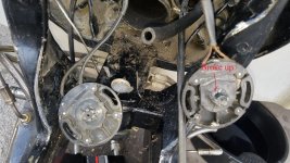
View attachment 333873
The seal is not needed if you have the non lube bearing. It just to hold the grease from getting to the bilge. If its greaseable, yes stick it in till its seated. Now is the time to replace them trim switches so you don't have to take the whole thing back apart to replace them when they fail soon .
 

gica

Chief Petty Officer
Joined
Feb 24, 2016
Messages
495
Yeah I just did the seal and bearing and it is the non-greaseable one but I already had the seal and put it in anyways.
20210215_162620.jpg
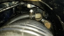
I also already got a new oil hose in and zip-tied, and the shift cable through.
i am changing the trim switches tomorrow.
Do the wires have positive and negative or it doesn't matter which of the 2 I connect to the designated port and starboard.
I will get the bellows installed and I read that only gimbal side get the adhesive is that true or both sides for the 2 large. I know the shift cable gets one side.
 
Last edited:

Grub54891

Admiral
Joined
Jun 17, 2012
Messages
6,079
The new trim senders have opposing bullet connecters inside the boat, and usually the Puck itself is labeled port/stb . The new wiring comes with the wire adapters for the old system.
 

gica

Chief Petty Officer
Joined
Feb 24, 2016
Messages
495
So I connected most of the stuff back to the bell housing and it wasn't easy. I installed all the bellows on the gimbal first including the shift cable, used the adhesive. It wasn't extremely difficult but anyways, have to be careful. I installed the oil hose which in my opinion should be installed first so that you have room to push, that's pretty difficult to do. I used a ziptie to secure it.
20210217_154213.jpg
The water hose you see mounted had to be removed as it has to go on the bell housing first. Than I put it in and had to spray WD-40 to get it to slide in and make sure already have the clamp in there before the hose.
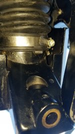
then came the bellows and I installed the exhaust shaft first, adhesive on bell housing also, and work it with the special tool. First 2 times I had to redo because it came out upon tightening it. But the 3rd time I made sure it was all the way up and I do think the adhesive also cured for the 10 minutes the manual recommends to wait so it is not tacky, and it held. Pain in the ass and might require 2 people and lots of light and patience. Tighten from below and the little tab/clip has to go underneath because otherwise when raising the motor it could snap out. That clip if original is bolted on to the bellow. I saw it in the numerous videos I watched.
20210217_161214.jpg
This is a picture from below.
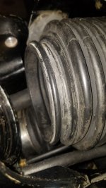
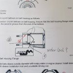
So now I am at the main bellow and in the manual it says to slide it to the second groove. I mean there's a raised lip on the bellow and a groove on the hpousing
I don't see 2 lips.
20210217_180149.jpg20210217_225916.jpg
20210217_225849.jpg
20210217_180715.jpg
And then to hammer the ring sleeve on does the bell housing have to be attached to the gimble?
Anyways that's where I am at right now
 
Last edited:

alldodge

Moderator
Staff member
Joined
Mar 8, 2009
Messages
42,071
I think you have the drive shaft bellows on backwards. Could also be the reason when tightening the clamp that it kept sliding off
 

Rick Stephens

Admiral
Joined
Aug 13, 2013
Messages
6,118
I think you have the drive shaft bellows on backwards. Could also be the reason when tightening the clamp that it kept sliding off
I didn't think they are close enough to the same size to put on backwards.... could be wrong. Is that OEM Mercruiser bellows going on or aftermarket?

It is going to go on the way it goes on. Whether it looks like the picture or not that groove has to line up with the bulge perfectly.
 

alldodge

Moderator
Staff member
Joined
Mar 8, 2009
Messages
42,071
One end has a double lip (bell housing end) the other side doesn't (transom end)

But you might be right with not the right bellows
 

gica

Chief Petty Officer
Joined
Feb 24, 2016
Messages
495
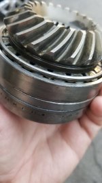
So because I have the drive apart I though of changing the seals on the upper part of the drive, so I got the tool and removed the gears. The thing I discovered is that the 2 bearings in the drive gear assembly don't spin freely at all. I have to hold the gear or put it back in the yoke and spin by hand and rag and when I stop twisting the bearings stop spinning. I have a feeling the shim after the drive gear is tightened on the bearing. This gear assembly does not come apart as soon as the nut is removed, I believe it is pressed in. So I need help with the next steps.
20210224_160938.jpg

Below is a video placed on Dropbox showing the spinning process.
https://www.dropbox.com/s/lrfa66pe5h...embly.mp4?dl=0
The boat is a 97 model with the Alpha one Gen 2 so which assembly is this the 80ft/lbs torque, or the 6-10 in/lbs one. There seem to be 2 or more different ones with different ways to adjust preload.
 

Rick Stephens

Admiral
Joined
Aug 13, 2013
Messages
6,118
I have to ask, do you have the proper Alpha 1 Gen 2 service manual? If not, you will have issues. Torque settings, lube types, where to use thread lock, which direction seals face and a lot more necessary points of interest.
 

Lou C

Supreme Mariner
Joined
Nov 10, 2002
Messages
12,693
I'm wondering why you pulled the drive apart, if there was no operational problem or water in the gear oil?
 

gica

Chief Petty Officer
Joined
Feb 24, 2016
Messages
495
I am beginning to wonder myself. The bearings were spinning a little slower than these newer ones are by hand. I mean really hard to spin. Initially wanted to just do the seals only but when reading about the bearings preload and how they should spin I decided that they were too tight.
I just did the preload with the dial and got it around 6 to 7 when I turn it with the dial. If I move faster it goes to 8 but only if I do it all around 360 full circle. The lady in the above video only spins it a little.
 

gica

Chief Petty Officer
Joined
Feb 24, 2016
Messages
495

Rick Stephens

Admiral
Joined
Aug 13, 2013
Messages
6,118
Now I don't recall how deep I went with each, but I used regular driver and mostly just made sure I was square and lips facing right direction. Depth can vary and not hurt anything 'cept a purists opinion. That was many years ago on a running Gen2. Musta done sumthin right.
 

Grub54891

Admiral
Joined
Jun 17, 2012
Messages
6,079
One seal keeps the water/debris out, the other keeps the oil in. Regardless, if the seal rides on a good smooth part of the shaft it should be fine. If the shaft has a wear line from the old seal it would be beneficial to have it in a slightly different location.
 

gica

Chief Petty Officer
Joined
Feb 24, 2016
Messages
495
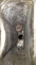
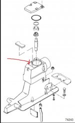
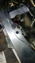
So I wanted to ask if anyone know what that silver ball down in the shaft see picture below?

20210403_184244.jpg
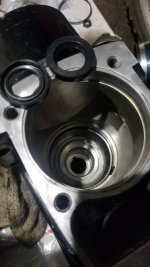
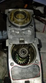
The ball inside there, underneath the Stuffer Plug, doesn't move so before I put the top cover back want to make sure this is not a problem. It's right next to the Upper Driven Gear Assembly compartment.
20210403_184526.jpg
Upper Drive.jpeg
 

todhunter

Canoeist
Joined
Sep 15, 2020
Messages
1,311
Just a wild guess, but it may be there to seal off a passage that was required during the manufacturing process but no longer needed for the part to function. I've seen this on throttle bodies before, where they fill a drilled hole with a steel ball and "stake" the aluminum around it to seal it in place. Again...purely a guess on my part.
 

gica

Chief Petty Officer
Joined
Feb 24, 2016
Messages
495
I hope that's all there is. I hammered it a bit and it kind of went down, maybe it is my imagination. From the flipside the oil hole doesn't seem to have access to the ball.
20210404_001633.jpg
 
Top