Force 70HP 1991 2 stroke Wiring Diagram

ninamy

Cadet
Joined
Apr 10, 2021
Messages
14
Dear iBoats members,

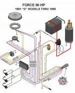
I'm new to this forum, i was redirected here in my search of an wiring diagram for my Force 70HP 1991 outboard motor.

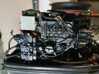
I bought this motor with the knowledge that the wiring is a disaster and now i'm trying to fix things, the startmotor works, trim/ tilt works also but i don't have an spark...

I saw an old threat on this forum with the same question but the URL in the responses doesn't work anymore.

So i need to know which wire is what for, i found an diagram on the internet which is in my opinion the good one (attached) but there is no explaination about which wire is what for (tachometer, battery charging...).

I hope someone can help me out, thanks!
 

Attachments

  • 90HP_1991D-1995.jpg
    90HP_1991D-1995.jpg
    95.1 KB · Views: 52

jerryjerry05

Supreme Mariner
Joined
May 7, 2008
Messages
18,053
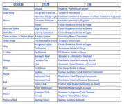
They standardized the color code sometime in the late 70's or early 80's
I found this by looking on Google and using the term "color code for marine wiring"
This should get you close.
1618135164366.png
 

ninamy

Cadet
Joined
Apr 10, 2021
Messages
14
Thanks!

I see a couple of wires that are corresponding, i'm gonna try it!
 

ninamy

Cadet
Joined
Apr 10, 2021
Messages
14
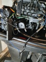
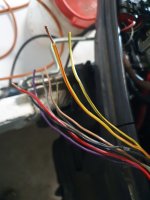
Now i'm facing the following: the old owner did cut the 8 pin connector off.

So i have an 3rd party contact switch but i need to know which wires should make contact with eachother when in Off mode, On mode, Start mode and i can push the key in to Choke i think...
 

Attachments

  • 20210411_125942.jpg
    20210411_125942.jpg
    1.7 MB · Views: 11

pnwboat

Rear Admiral
Joined
Oct 8, 2007
Messages
4,251
For starters, it looks to me like you might have the wrong stator.

The stator wires should be the following colors. 2 Yellow wires that go to the Regulator/Rectifier. 1 Blue wire that goes to the "BLU" terminal on the Switch Box. 1 Red wire that goes to the "RED" terminal on the Switch Box.

The terminals on the Switch Box labeled "BRN, "WHT", "VIO", and WHT/BLK are for the ignition trigger coils.

The terminals labeled "GRN", "GRN/WHT" and "GRN/RED" go to the ignition coils.

The terminal "BLK/YEL" goes to the ignition Kill circuit.
 

pnwboat

Rear Admiral
Joined
Oct 8, 2007
Messages
4,251
I'm looking at the wires where the 8 pin connector was cut off. Don't take this as gospel, as wire colors may change from year to year.

Yellow/Black = Choke or Primer solenoid.
Red = Battery positive 12 volts. Might run to the fuse just above the Regulator/Rectifier.
Black = Engine ground.
Black/Yellow = Ignition Kill circuit.
Gray = Tach connection on the Regulator/Rectifier.
Yellow/Red = Neutral start switch.
Violet = not used or goes to the tach connection on Regulator/Rectifier
There's one wire that looks kind of like Tan/Black. It might go to the overheat sensor on the head. Not sure about that one.....
 

ninamy

Cadet
Joined
Apr 10, 2021
Messages
14
Yes, i found everything out and connected it to an Sierra 6 wire key switch on the right positions.

Unfortenatly i still don't have an sprak on the spark plugs:(
 

pnwboat

Rear Admiral
Joined
Oct 8, 2007
Messages
4,251
You don't have a red stator wire attached to the "RED" terminal on the switch Box because I suspect that you don't have the correct stator. What color are your stator wires?
 

ninamy

Cadet
Joined
Apr 10, 2021
Messages
14
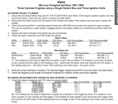
I have a red stator, with 2 yellow wires, a white/green and a green/white.

That's also why the "candybar" adaptor is between it and i've red somewhere on a forum that with that stator there is no need for the red wire?
 

ninamy

Cadet
Joined
Apr 10, 2021
Messages
14
Here you can see the white/green and green/white wires are original with the Red stator...
 

Attachments

  • 2021-04-11 21_22_06-Tech-Guide-Digital.pdf.png
    2021-04-11 21_22_06-Tech-Guide-Digital.pdf.png
    172.6 KB · Views: 13

pnwboat

Rear Admiral
Joined
Oct 8, 2007
Messages
4,251
You have a later model stator that is typically used in the CDM ignition system from around 1994 and later. The trouble-shootong page you posted is a bit misleading in your case because they don't tell you what years the Black stator and Red stators were used. As far as I know, OEM Switch Box stators were black and had the Blue and Red stator wires. I suspect that someone has replaced the stator on your motor and used the wrong stator. Your ignition system was designed to use a different stator that has seperate low speed and hig speed stator windings. It should have a Blue and Red stator wires. They attach to the Switch Box terminals marked "BLU" and "RED". The pictures you posted, show there is no wire on the Switch Box terminal marked "RED". The Blue wire that is attached to the Switch Box terminal marked "BLU" comes from the "candy bar" adapter, not from the stator. At least it looks that way from the pictures. So from the pictures, it appears that you do not have any wires from the stator attached to the Switch Box. If this is the case, then there is no way that you will get any spark.

One other thing, where are the Green/White and White/Green wires on your current stator hooked up to?
 
Last edited:

ninamy

Cadet
Joined
Apr 10, 2021
Messages
14
Ah, that could be the case then...

The 2 green wires from the stator are ging in the candybar...
 

ninamy

Cadet
Joined
Apr 10, 2021
Messages
14
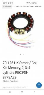
As i can see on Ebay should this be the correct stator:

8778A29​


But i see 6 wires instead of 4...
 

Attachments

  • Screenshot_20210412-081905_Chrome.jpg
    Screenshot_20210412-081905_Chrome.jpg
    409.5 KB · Views: 10
Last edited:

pnwboat

Rear Admiral
Joined
Oct 8, 2007
Messages
4,251
Yes that is the correct one. If I remember correctly, the installation instructions for this particular stator on the CDI WEB site says to run the Red/White and Blue/White wires to engine ground. The original stator had the windings internally wired to ground. I think I saw a used one on Ebay for less than $50. But you're taking a chance.


I think you can test to see if your Switch Box is good using the stator that you have right now. Run one of the stator wires to the candy bar, and attach the blue wire from the candy bar to the Switch Box like you have it now, and the other stator wire to engine ground. Doesn't matter which stator wire. There is no polarity. The stator that you have has the same voltage output and resistance as the original stator's low speed winding. Crank the motor over and see if you get spark. If not, disconnect the Black/Yellow wire from the Switch Box. This is the ignition Kill circuit. By disconnecting it, you are disabling it. Check for spark again, If no spark, then you may have a bad Switch Box.
 

ninamy

Cadet
Joined
Apr 10, 2021
Messages
14
I think i found the problem, i measured the voltage coming from the stator, this should be between 180 and 400 volts but it is 135 volt, so i think the starter is not making enough RPM's for the spark...
 

pnwboat

Rear Admiral
Joined
Oct 8, 2007
Messages
4,251
That could very well be, however, if you aren't using a DVA you will get incorrect readings. See link below.
DVA adapter

To get the engine to spin over faster, you can pull all the spark plugs and ground the ones that you are not checking for spark. Even if the stator was only producing 135 volts, I would think that should be enough to get a weak spark. That's just my thoughts but I could be wrong.

Forgot to mention that you might want to check the resistance between the Green/White and White/Green stator wires. Make sure the wires are not connected to anything. You should read between 500 and 700 ohms.

Also, some of the cheap meters don't measure this type of voltage very accurately.

Unfortunately, the Switch Box is a very common failure item with this type of ignition system. I wouldn't assume it is bad until you get the correct stator and do further tests.
 
Last edited:

ninamy

Cadet
Joined
Apr 10, 2021
Messages
14
Thanks for your reply!

A couple days further of thinking what it could be i figured out it is not the starter. Bought a new one and it goes faster but not an significant change.

I also figured out the following:
every time i come at my storage to try to start the engine i have an spark, so when i finally think, yes this is it and put the sparkplugs back in the engine the spark is gone. When i take them out: no spark anymore.

So in my opinion i think the following is the case:
I think an component in my switchbox becomes warm after like 200 sparks and then stop to give any power to the sparkplugs. I found a new switchbox on aliexpress.com for 20 euro so i bought it.

Today i googled the difference between the black and red stator and i found the following post on this forum: https://forums.iboats.com/threads/sport-jet-120-stator-red-vs-black.409943/

So it seems like the red stator is good for me, but it also tells me the switchbox could be the issue...
 

pnwboat

Rear Admiral
Joined
Oct 8, 2007
Messages
4,251
I'm not 100% sure that the red stator is the correct one for the Switch Box that you have. The Switch Box that you have looks to me like it has inputs for a high speed stator winding and a low speed stator winding. You are only using the input for the low speed winding with the red stator. If this is the case, you may not get the best performance from your ignition system at higher RPM's.

There are several versions of the red stator. You have to look at specific part numbers. Some red stators are 9 amps battery charging output, some are 16 amps battery charging output. It appears that the one you have is not designed for the Switch Box ignition system.

Hopefully the Switch Box resolves your intermittent spark issue. 20 euros seems almost too good to be true! (Unless it is used.)
 
Top