Force 50 HP. Rain got in key switch. Wires smoked. Now Cranks but No Spark.

777funk

Petty Officer 2nd Class
Joined
Jan 12, 2015
Messages
150
I started this thing like normal yesterday morning but noticed smoke was let out near the key switch. When I went to restart before taking it out to the lake, I was presented with a no start condition. I pulled one high tension plug wire at a time and connected to a chassis grounded spare spark plug and there is no spark at either cylinder.

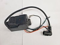
So something must have burned at the key switch creating the no spark condition. I don't know much about the key wiring. Where do I begin to look? My two coils look like this. I'm guessing this is a CDI. I see 4 wires plus ground and the plug lead on each coil. So probably a pair for AC voltage in from the stator and a pair for the trigger signal. I am a little familiar with the CDI itself but have no idea where to look from the key switch on as far as a run/stop signal. Any tips would be greatly appreciated!
 

Attachments

  • force_50HP_Coil.jpg
    force_50HP_Coil.jpg
    143 KB · Views: 1

777funk

Petty Officer 2nd Class
Joined
Jan 12, 2015
Messages
150
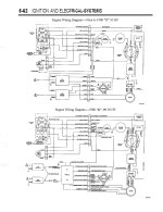
1988 (Prior to D) model.
I just measured the stator and trigger coils resistances and they seem to be in spec:
700 ohms for stator
48 ohms per trigger coil
130 ohms spark plug wire to ground

The one value I'm not at all sure about is that the brown shut off wire from one CDI pack to the other (brown wire to brown wire) measures 700 ohms (each brown wire from one or the other coil pack is measuring zero ohms to one or the other end of the stator coil) and open circuit from each shut off wire to ground. These two brown wires (shut off) go to the key switch via a white and a blue wire. They're shorted together to kill the engine.

I have no idea which wires were smoking behind the ignition switch before the problem.
 

Attachments

  • Force_50HP_electrical_diagram.jpg
    Force_50HP_electrical_diagram.jpg
    254.1 KB · Views: 5
Last edited:

Jiggz

Captain
Joined
Oct 23, 2009
Messages
3,909
You would have to dismount the ignition switch and investigate which wire smoked. If there is smoke there sure is either a melted insulation or even melted contacts inside the ignition switch. For troubleshooting, you can also disconnect the brown (shut down) wires from the terminal board in the engine compartment. Cranking it over should start the motor, Note be ready to shut it down by grounding the brown wires as the ignition sw will not do it as the wires are disconnected. I usually use a short jumper with alligator clips. Insulate yourself when doing this as the wires are charged.

If this does not allow the motor to run and there's still no spark then you know the problem is in the CDI modules or the stator. And the problem with CDI or CD modules or Ignition coils is that the only way to test is by having a spare known working one.
 

777funk

Petty Officer 2nd Class
Joined
Jan 12, 2015
Messages
150
I tried disconnecting the two magneto terminals on the key side the day it happened and no start. I tried on the engine side yesterday afternoon and also no spark. Going to try disconnecting and measuring the rectifier for a short or just cranking with it disconnected.

I measured 300VAC from the stator coil yesterday but nothing from the triggers. Of course this is without a DVA but I figured I'd see something from the trigger coils. I have a $40 hand held oscilloscope, that should show pulsing from the trigger coils (I'd think) if they're ok.

Everything from the key switch (start, choke, run/kill signal) still works so I'm not sure what the smoke was coming from. My guess is that it somehow put battery voltage to the stop side of the CDI.

Does anyone know what CDI to CDI Brown kill wires should measure in ohms? I'm getting around 700 ohms which I'm guessing is the stator reading through the kill wires on the CDI. Just not sure if that's supposed to be the case. This is the 1988 model prior to D with a CDI as pictured above.
 

Jiggz

Captain
Joined
Oct 23, 2009
Messages
3,909
When reading trigger output voltage and stator output voltage make sure you read between proper pair of wires from each unit. Trigger voltage is really very low. As low as 0.5VAC hence reading it without a DVA adapter makes it almost impossible. But with a handheld os-scope you should see the pulse just make sure you set the sensor to its highest settings and not attenuated.
Other things to check if there is voltage from trigger wires: Do continuity on:
Black wires from CDI to ground
Disconnect the rectifier entirely from both sides, i.e. alternator AC (yellow) and output red and black wire and also the purple rpm/tach wire. This is in addition to the disconnected shut down brown wires mentioned earlier.
This is about the most isolation you can do and if the problem persists, you would have to start replacing stuff with known working parts. And I will start with one CDI only. At least this will give you a spare for the future.
 

777funk

Petty Officer 2nd Class
Joined
Jan 12, 2015
Messages
150
I tested the Trigger Coils with the hand held o-scope and am getting signal but it's only 1 VAC or less. Not sure if that's ok or not. Both read the same. I'm not sure that a magnet hasn't come loose from the flywheel but probably not since the stator coil is putting out 300 VAC. I'd assume the same magnet is doing the high voltage stator supply as the triggers. So the magnet must be intact.

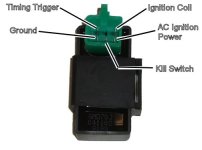
I may try one of these cheap Honda CDI packs (5 pin) and a Honda coil running from the stock stator and trigger and see if that gives spark. I don't know how two Force CDI/coil units could fry at the same time. But there was smoke from the ignition so maybe somehow that's what happened. The only thing I could imagine happening was 12VDC going to the kill terminals on the key switch. Maybe maybe not there.
 

Attachments

  • 50cc-cdi.jpg
    50cc-cdi.jpg
    19.2 KB · Views: 1
Last edited:

Jiggz

Captain
Joined
Oct 23, 2009
Messages
3,909
The 1VAC from the trigger is good output. There are two sets of magnets on the underside of the flywheel. On the outer perimeter is the magnet for the stator while on the inside (there is casting around the flywheel hole to reinforce it) is the set of magnets for the trigger.

As for the ignition switch, there is no 12VDC going to the kill switch nor is there any power from the ignition switch going to the CDI. The "B" terminal connects to the battery through the starter solenoid and rectifier (parallel and not series). This battery power is for accessories and T&T if you have one. There are two "M" terminals, one connects to ground while the other connects to the shut down wire (brown) of the CDI. In off position of the ignition switch, these two "M" terminals are shorted or closed, hence shunting the CDI to ground and preventing if from creating sparks and shutting down the motor. A safety lanyard switch is in parallel with these two "M" terminals and is normally closed. However, a pin or key is inserted to keep it open. A lanyard or nylon line is provided for the operator to wear and in case the operator is thrown overboard, the lanyard will pull the key and allowing the switch to close, thus shutting down the motor preventing a runaway boat. There is also a "S" terminal which is for Starting. And finally, a "C" terminal which is for the choke system.
If you did all the electrical isolation previously mentioned, all together and still have no spark the only thing left is most likely is bad CDI's.
 

777funk

Petty Officer 2nd Class
Joined
Jan 12, 2015
Messages
150
The 1VAC from the trigger is good output. There are two sets of magnets on the underside of the flywheel. On the outer perimeter is the magnet for the stator while on the inside (there is casting around the flywheel hole to reinforce it) is the set of magnets for the trigger.

As for the ignition switch, there is no 12VDC going to the kill switch nor is there any power from the ignition switch going to the CDI. The "B" terminal connects to the battery through the starter solenoid and rectifier (parallel and not series). This battery power is for accessories and T&T if you have one. There are two "M" terminals, one connects to ground while the other connects to the shut down wire (brown) of the CDI. In off position of the ignition switch, these two "M" terminals are shorted or closed, hence shunting the CDI to ground and preventing if from creating sparks and shutting down the motor. A safety lanyard switch is in parallel with these two "M" terminals and is normally closed. However, a pin or key is inserted to keep it open. A lanyard or nylon line is provided for the operator to wear and in case the operator is thrown overboard, the lanyard will pull the key and allowing the switch to close, thus shutting down the motor preventing a runaway boat. There is also a "S" terminal which is for Starting. And finally, a "C" terminal which is for the choke system.
If you did all the electrical isolation previously mentioned, all together and still have no spark the only thing left is most likely is bad CDI's.
I have the pre-D ignition system where the two magneto shutoff wires (brown at the mag or White and Blue on the key and terminal strip) are shorted together when it turns off. My theory is the 12V Red at the key was somehow shorted to the magneto wires at the key (white and blue wires). The key switch is in poor corroded condition. Something happened and caused it to smoke then no spark on the next startup minutes later. But that's just a theory. Something happened that I'm guessing took out the CDIs.
 

Jiggz

Captain
Joined
Oct 23, 2009
Messages
3,909
OK, I see in your wiring that this is not the ground shunting type but as you mentioned shorting the two brown wires. As mentioned if these wires were isolated with the entire rectifiers too then the only fault could be the CDI. This is after verifying outputs on the trigger and stator are within specs. Obviously, the ignition switch needs to be replaced as well before moving on to install a new CDI for testing. And that ignition switch is much cheaper than frying another CDI.
 

ct1762@gmail.com

Master Chief Petty Officer
Joined
Jan 17, 2019
Messages
859
I almost always skip right to cranking voltage tests . resistance almost never shows anything interesting for me, as a component will often test fine only to fail a cranking voltage test. Part of a complete and thorough job resistance should be done, sure, but on the other hand if cranking voltage is fine but resistance is a bit off/uneven depending on part, it is still fit for service.
 

777funk

Petty Officer 2nd Class
Joined
Jan 12, 2015
Messages
150
I almost always skip right to cranking voltage tests . resistance almost never shows anything interesting for me, as a component will often test fine only to fail a cranking voltage test. Part of a complete and thorough job resistance should be done, sure, but on the other hand if cranking voltage is fine but resistance is a bit off/uneven depending on part, it is still fit for service.
Pretty sure the stator somehow burned. I was thinking it was reading 200V approx when cranking but I failed to notice the decimal point. It's generating 0.200VAC approx. So I would say either magnets are demagnetized (they do seem weak) or more likely somehow something weird happened to the stator. I still can't imagine what though. If 12VDC from the key somehow ended up on the stator, neither side is grounded so it'd be a floating 12 volts. I'd think nothing would happen. If both wires from the stator shorted together through the key switch, that'd also be ok since that's what happens when you turn the key to off anyways.

So the smoke and no run mystery has me baffled. Something took out the stator and smoked the wires and key switch.
 

ct1762@gmail.com

Master Chief Petty Officer
Joined
Jan 17, 2019
Messages
859
the only thing that can take out a stator like that would be burned out rectifier diode/s. .2v obviously is nothing. are you sure its not reverse-polarity?
 

777funk

Petty Officer 2nd Class
Joined
Jan 12, 2015
Messages
150
the only thing that can take out a stator like that would be burned out rectifier diode/s. .2v obviously is nothing. are you sure its not reverse-polarity?
This is the two blue wires for generating CDI energizing voltage. This is AC so there should be no polarity here. I need to check the rectifier feeding taps from the stator and the DC after the rectifier too and see if it's putting out battery charging voltage when cranking.
 

ct1762@gmail.com

Master Chief Petty Officer
Joined
Jan 17, 2019
Messages
859
you say its AC... well you are correct, however, DVA readings are always taken on DC setting!
 

Jiggz

Captain
Joined
Oct 23, 2009
Messages
3,909
This is the two blue wires for generating CDI energizing voltage. This is AC so there should be no polarity here. I need to check the rectifier feeding taps from the stator and the DC after the rectifier too and see if it's putting out battery charging voltage when cranking.
The alternator windings in the stator usually do not produce sensible voltage at cranking speed. In fact, it takes around 2K rpm for the charging voltage to get started. You can try but I doubt you'll see anything on the DVM.
 

777funk

Petty Officer 2nd Class
Joined
Jan 12, 2015
Messages
150
Ok you guys talked me into building a DVA. It's still reading very low on charging and spark generating coil. Like right around a volt DC there.

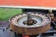
I think I found the problem. Still not sure why the smoke however. The magnet had come unglued from the flywheel due to rust, heat, and time (it is a 1987 after all). It's a flexible strip of ceramic magnet that was glued around the inside circumference of the flywheel. I pulled the flywheel and the band shaped magnet stayed with the stator. It was easy to remove from the stator. Now I will have to glue it back in. I'm thinking Epoxy.
 

Attachments

  • IMG_3481.JPG
    IMG_3481.JPG
    3 MB · Views: 2

Jiggz

Captain
Joined
Oct 23, 2009
Messages
3,909
There was a post in here asking for the best glue for magnets. And one member actually post a glue for magnets used on Evinrude motors. You might want to search it.
 

777funk

Petty Officer 2nd Class
Joined
Jan 12, 2015
Messages
150
There was a post in here asking for the best glue for magnets. And one member actually post a glue for magnets used on Evinrude motors. You might want to search it.
I will probably use my West Systems standard marine epoxy since I have it on hand and don't want to spend $75.

But here's what I found in another thread here (looks to be good info):
Re: gluing magnets to flywheel

Thank you guys for the info.I did find out that OMC makes an epoxy p/n 0431929 that CDI told me about.It does not say it works on magnets but they say it does.I had already ordered a new product made by loctite for magnets,Loctite 331 & activator 7387.It cost me $75 so I felt compelled to use it.It can be ordered thru FASTENAL.COM......THANKS AGAIN for the help....That epoxy can be had at marineengine.com.dargel 167
 

Jiggz

Captain
Joined
Oct 23, 2009
Messages
3,909
Some people had luck with standard JB Welds and epoxies. So give it a shot and hope it holds.
 
Top