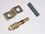
Drilling a hole in the water jacket cover for the installation of a temp sending unit

GT1000000

Rear Admiral
Joined
Jul 13, 2011
Messages
4,916
Alrighty then, my brain is on overload and feeling quite frazzled!
I have spent the last few days looking through every post related to installing a temperature sending unit/ temperature gauge in a Merc.
I have found an untold wealth of knowledge, but nothing directly related to my current needs.
I have also been through several dozen pages of YouTube videos related to Mercury outboards and I still haven't found exactly what I am looking for.
I have perused several other Mercury Outboard related sites and got zip, zilch, nada, nothing, bingo...:confused:
I am hoping that someone in the Iboats Universe has done this project and can point me in the right direction.

The Project: Install a temperature sending unit in the port cylinder head of a 1989, 200 HP, V-6 Mercury Outboard.
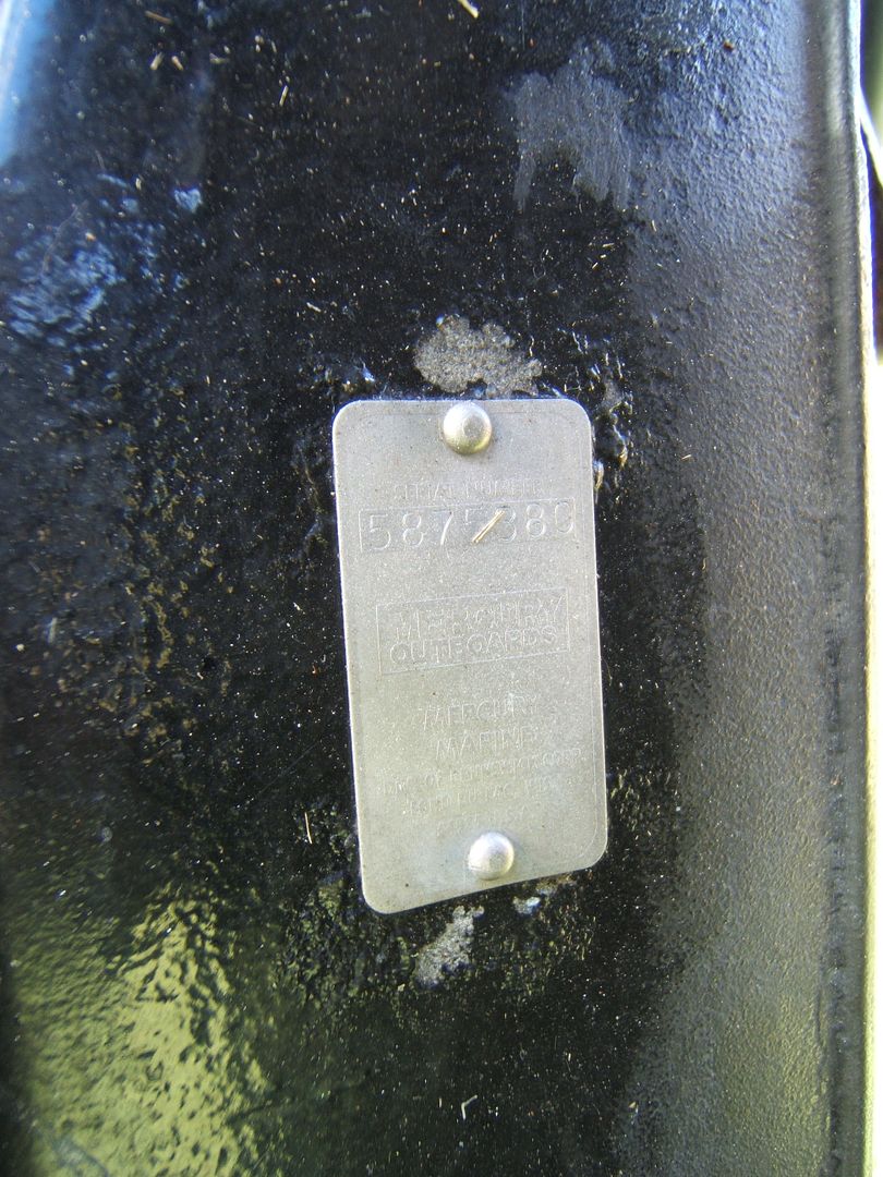
Engine Serial # 5875380

What I already know...

1- Unless I have a spare wire in the engine harness that leads to the helm, I will have to run a new wire...got that! Check!
2- I am aware that there are kits available for doing this, but it is too late, already purchased a temp gauge and a sending unit, separately, so I have NO kit to speak of...
3-I have read and seen where it is possible to install the sending unit using a Z bracket and having the sensor just making contact with the top of the cylinder head...I am not too keen on this method, as I would rather have the sensor/sending unit in direct contact with the raw water that is circulating in the engine for a more accurate reading.
However, if this is the recommended way by the experts, then that is how it will get done...
4- The engine is equipped with thermostat(s)...I am not certain if one or two and I would prefer not to open up the housings unless absolutely necessary...
5- The engine currently does not have a tell tale hooked up, but I will be installing a tee for one...which, if any of you is taking the time to read through all of this and would like to offer an opinion as to the best place to install the tee, I would really appreciate it...;)
6- Just in case, the temp gauge is a Faria unit that reads from 100?-250?, it requires a sending unit that reads 450Ω @ 100? and 33Ω @ 250?, the sending unit purchased from Iboats.com sends 450Ω @ 100? and 46Ω @ 220?...close enough for gubmint werk...
8-The engine is equipped with a High Temp alarm, but I feel that by the time it goes off, it might be too late...
9-I am also aware that a water pressure gauge is good to have, but that will have to wait till more funds are available...this is a project I am doing for one of my co-workers and we have what we have for now, so skip the advice on the installation of one, thank you...:watermelon:

What I need to know to accomplish this project...
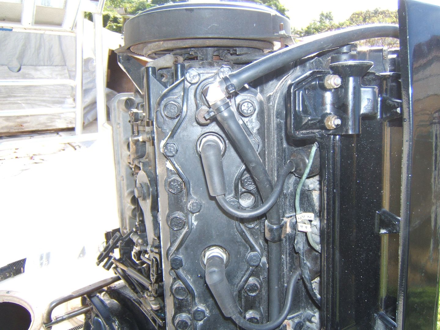
1-What is the correct spot on the port water jacket cover to drill and tap for the installation of the sending unit? There is no spot on the cover that is clearly marked that would indicate the correct placement of the ending unit.
I would like to avoid, if possible, the removal of the cover, but I would like to be certain that where I drill, is not going to harm the engine in any way, obviously.
2-Are the few shavings of the drilling that fall into water jacket of any consequence? Or will they just flush out...
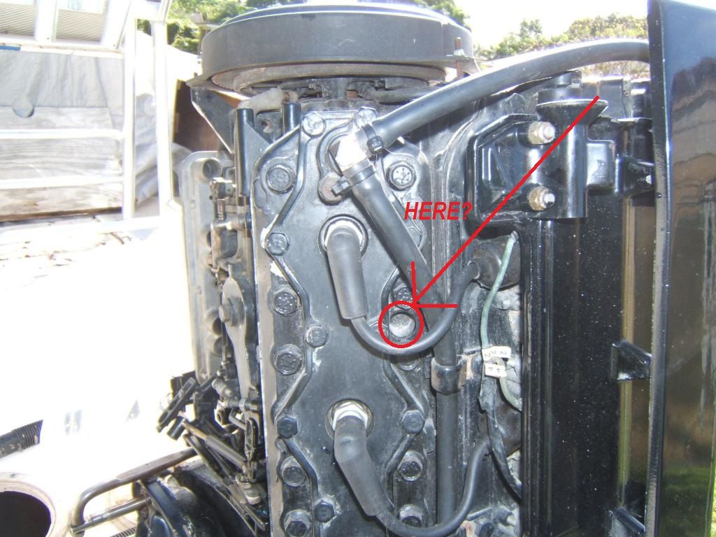
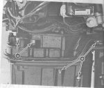
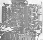
Here is a pic of the port cylinder head...It shows a recees between cylinders 1 & 2...on the starboard head, this is where the Hi-Temp Alarm Switch is installed...

Thank you all in advance for taking the time to read and offer any suitable advice.
Happy Thanksgiving!,
GT1M:D


Silvertip

Supreme Mariner
Joined
Sep 22, 2003
Messages
28,771
Re: Drilling a hole in the water jacket cover for the installation of a temp sending

It's a little late for this information but you could have bought just the sender and used a single gauge along with a switch that selects port or starboard head temp. But you will have two gauges so that's moot. If you want to drill a hole go ahead. Just make sure where you are drilling gets you into the water jacket. The safe way to determine this is to remove the water cover so you can see. Understanding water flow through y0ur particular engine is also important. You want to measure the hottest area of the block.
 

Faztbullet

Supreme Mariner
Joined
Mar 2, 2008
Messages
15,920
Re: Drilling a hole in the water jacket cover for the installation of a temp sending

1989, 200 HP, V-6 Mercury Outboard.Engine Serial # 5875380
Uh... first off its a 80 or 81 model not a 89 year.. 2nd you dont want to drill into water jacket as depending on where drilled you could read only water into jacket which would be colder than actual motor. Just remove the water jacket bolt next to OEM sender hole and install a Z shaped thread bracket to hold sender in bottom of hole. Post a close up pic or see what head casting is as that dont have a 200 front air box on it. Bore size will be cast on head in oval area 3 3/8 for
 

Dukedog

Captain
Joined
Oct 6, 2009
Messages
3,428
Re: Drilling a hole in the water jacket cover for the installation of a temp sending

Uh... first off its a 80 or 81 model not a 89 year..

Good catch Fb. 1st generation block. Its OLD...............Also looks like ta have a vertical front (150 or 175 depending on bore size)
 

GT1000000

Rear Admiral
Joined
Jul 13, 2011
Messages
4,916
Re: Drilling a hole in the water jacket cover for the installation of a temp sending

Uh... first off its a 80 or 81 model not a 89 year..

Got it thanks, I either misread the crappie Seloc manual or it has bad info in it...nothing new there...plus I was going off of what the owner told me had, prolly also a bunch hooey...:rolleyes:

2nd you dont want to drill into water jacket as depending on where drilled you could read only water into jacket which would be colder than actual motor. Just remove the water jacket bolt next to OEM sender hole and install a Z shaped thread bracket to hold sender in bottom of hole.

OK, I understand...
The recess that is shown in the pic? RED Circle/Arrow?


Next part of the questions is...
Do I need to scrape off the paint in the bottom of the hole to insure an accurate reading, or just make sure I have a tight connection?

Post a close up pic or see what head casting is as that dont have a 200 front air box on it. Bore size will be cast on head in oval area 3 3/8 for

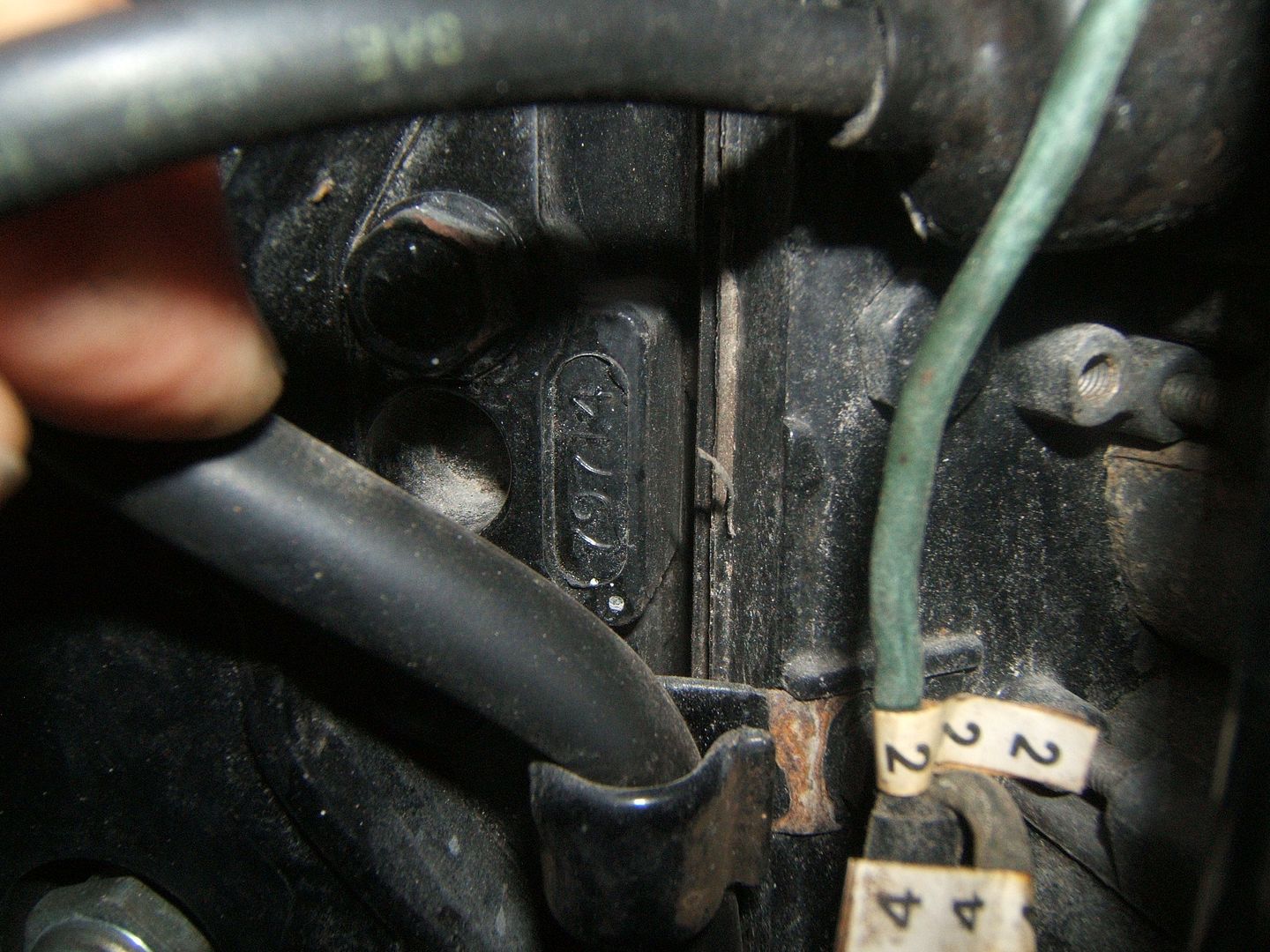
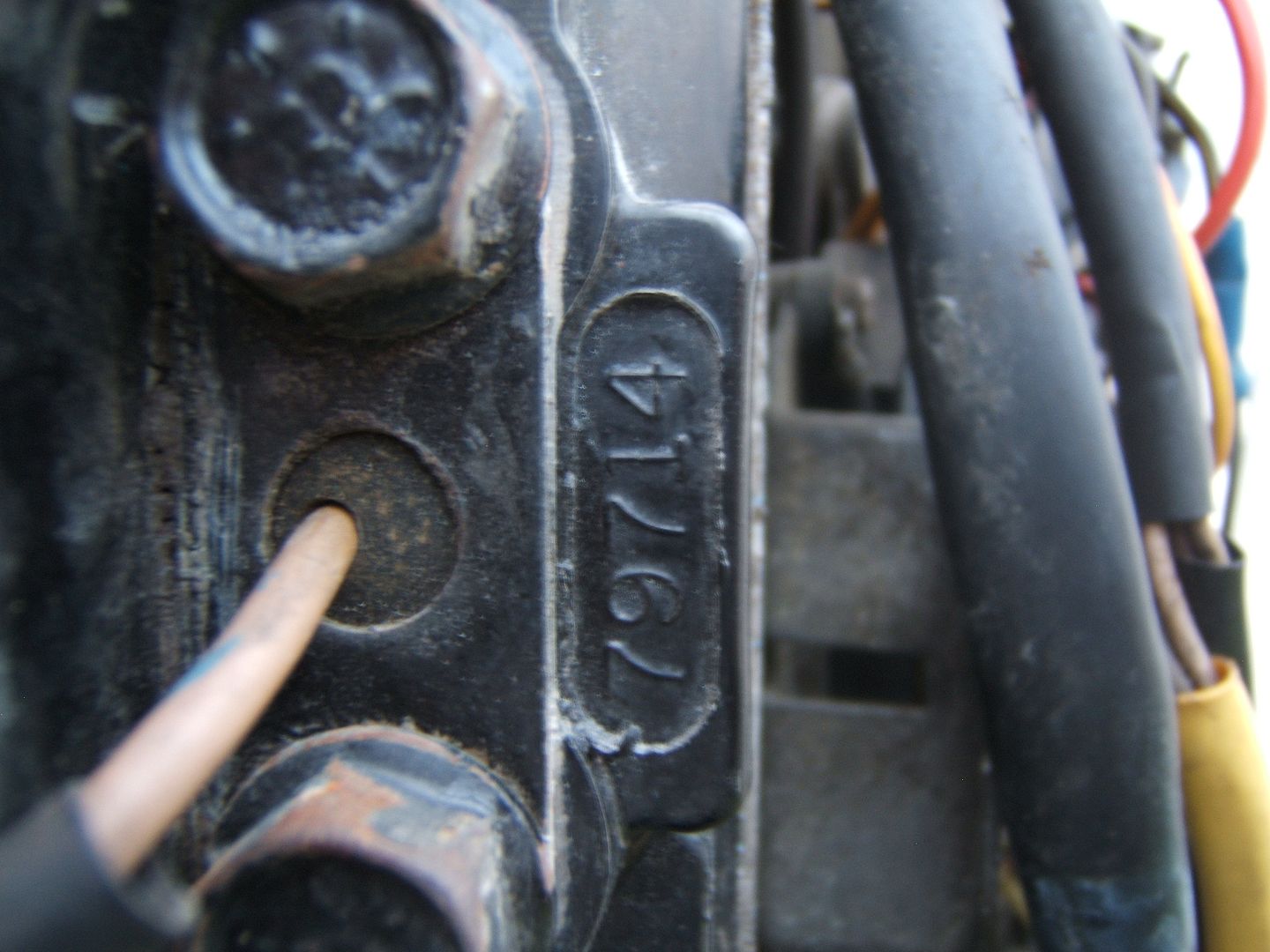
Here are the head casting #'s 79714
Port...

Starboard...


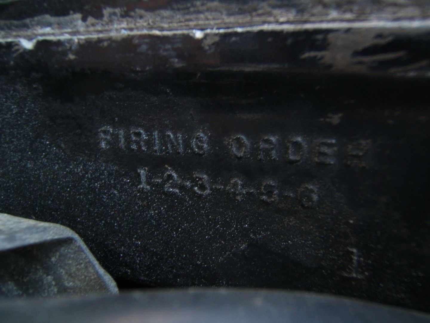
Firing Order;1-2-3-4-5-6... if it makes any difference...


Let me know if you need any other info...
Thanks!:D
 

sam am I

Commander
Joined
Jun 26, 2013
Messages
2,169
Re: Drilling a hole in the water jacket cover for the installation of a temp sending

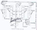
Wondering though and perhaps merc changed the cooling/water flow path/s from 80, 81 but, in my 92 and here in the schematic, any water entering and/or residing in the cylinder head has to have moved/flowed past the pistons/cylinder walls. It has two ways to leave the cylinder head though, through the thermostat(open) or poppet(higher speed/pressure).

So I would assume measuring water temp anywhere in the casting of the cylinder head, would be/is a mix of the 3 cylinders after it flowed out of the heads BUT, it HAS to be flowing!! So there will always be latency but conduction will be heating that water up else thermostats would never open at idle for example.

There are though little drain holes leading directly from the cylinders (they're shown in the schematic and labeled as "drain passages") into the mid section/exhaust plate, those would be the best and most instantaneous water temps reflective of cylinder temps. Not sure how'd a guy instrument those tho.

I'd not be wanting to be drilling into the heads/engines though. I'd go with using those factory set area/s as suggested above and yes, use silicone thermally conductive grease. Merc uses something like this, both my temp sensors have it smeared on them.

And yes ideally, clean of any paints, rust, etc, etc, from surfaces that heat transfers from and too, and apply the thermal grease between the two. This will reduce thermal resistances and the grease will provide/ensure the best thermal conductivity. Will it work within a 10% tolerance not too do either? Probably.

Oh and, the schematic should help you w installing the tell-tail.

GL

http://www.dowcorning.com/content/publishedlit/11-1712-01.pdf


http://www.biggerhammer.net/mercury/waterflow_89newer_2.4_2.5_blizzard.jpg
 
Last edited:

Dukedog

Captain
Joined
Oct 6, 2009
Messages
3,428
Re: Drilling a hole in the water jacket cover for the installation of a temp sending

Look at tha "base" of number two (top port cyl.)cylinder, on tha block half (back half). Kinda behind tha advance timin' arm. There will be a build date stamped in that area somewhere. It will be 1/8" numbers. m/d/yr. Like Fb said, look on tha head for a small "circle" with bore size stamped in it. Will be either 3 1/8" or 3 3/8". With one of those numbers and a picture of tha port "side" of tha motor can tell what tha hp is.......
 
Last edited:

Faztbullet

Supreme Mariner
Joined
Mar 2, 2008
Messages
15,920
Re: Drilling a hole in the water jacket cover for the installation of a temp sending

If I remember right that motor should have the "p" indicator coming off the adapter plate and the hoses on t-stats reversed as port goes to starboard and starboard to idle shut off/poppet valve. That part number is a 2.4 if I remember as the 79714 is a 150/175
 
Last edited:

Dukedog

Captain
Joined
Oct 6, 2009
Messages
3,428
Re: Drilling a hole in the water jacket cover for the installation of a temp sending

Here ya go.............
 

Attachments

  • waterflow%2089%20and%20older%20v6.jpg
    waterflow%2089%20and%20older%20v6.jpg
    80.9 KB · Views: 2

Faztbullet

Supreme Mariner
Joined
Mar 2, 2008
Messages
15,920
Re: Drilling a hole in the water jacket cover for the installation of a temp sending

You sure it not like this Dog????

Scan.jpgScan1.jpg
 

Dukedog

Captain
Joined
Oct 6, 2009
Messages
3,428
Re: Drilling a hole in the water jacket cover for the installation of a temp sending

On first generation there are three different poppets best I remember. 1 two bolt, no bib. 1 four bolt, no bib. 1 four bolt with bib. Think tha 150 was a 2 bolt cover (no hose bib) and tha 175/200 had tha 4 bolt with a bib. Might have been just tha '77 ta '79 that were different?. I do remember there was a difference with some. Just a little foggy for me. If his has tha 4 bolt with tha hose bib then what your showin' is right. Gettin' old just barely beats tha alternative...........
 
Last edited:

GT1000000

Rear Admiral
Joined
Jul 13, 2011
Messages
4,916
Re: Drilling a hole in the water jacket cover for the installation of a temp sending

Thank you very much, gentlemen...
With the info provided I believe I should be able to accomplish both tasks at hand as soon as I get some more free time.
I will provide the requested info as soon as I get to it.
The pics and diagrams go a long way to helping me figure out where to put to tell tale line.
As soon as I get things squared away, or if I run into any more issues, I will post up.
Again, Thanks for all the help!
Have a great day!:D
 

banshee owner

Petty Officer 1st Class
Joined
Sep 4, 2013
Messages
227
Re: Drilling a hole in the water jacket cover for the installation of a temp sending

OK gt1m since i cant really give you any USEFUL info i only going to mention that you forgot step number 7 in your original post so im going to substitute one for you

#7 if i don't figure this out im drink myself silly tonight and worry about it tomorrow

lol
 

GT1000000

Rear Admiral
Joined
Jul 13, 2011
Messages
4,916
Re: Drilling a hole in the water jacket cover for the installation of a temp sending

OK gt1m since i cant really give you any USEFUL info i only going to mention that you forgot step number 7 in your original post so im going to substitute one for you

#7 if i don't figure this out im drink myself silly tonight and worry about it tomorrow

lol

You know, you are absolutely right, I did leave that very important step out, thanks for clarifying!;):laugh:

BTW, I got the needed supplies for the installation of the sending unit and the Tee for Pee...
Hopefully have some time tomorrow to work on it...
Pics of any progress to follow any progress made...:D
 

GT1000000

Rear Admiral
Joined
Jul 13, 2011
Messages
4,916
Re: Drilling a hole in the water jacket cover for the installation of a temp sending

OK, ran into a small snafu today...
I just realized that to mount the temp sending unit as described will require the removal of at least one, maybe two, of the Cylinder HEAD bolts...NOT the water jacket bolts...referring to the picture in post #5...
My concerns are...
1-The possibility of breaking
2-Integrity of the head gasket seal, after removal and replacement, re-torqueing...
Should I even be worried, or are there any precautions I should take beforehand?
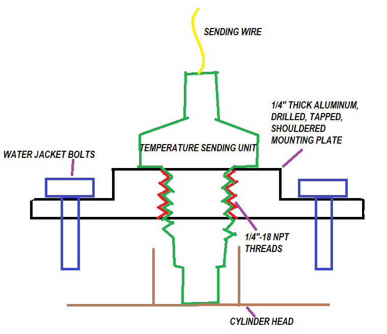
My idea is to make a mounting bracket out of 1/4" thick aluminum...like the sketch below...I even named the bolts incorrectly in the sketch, they are actually the head bolts I am asking about...


TIA:)
 

Faztbullet

Supreme Mariner
Joined
Mar 2, 2008
Messages
15,920
Re: Drilling a hole in the water jacket cover for the installation of a temp sending

Just use a "Z" bracket like in pic below and use the water jacket bolt next to hole. Its not going to be accurate but will give ya a idea of temps, best to use a water pressure as you can watch t-stats and poppet open/close,water pump condition and tell instantly of loss of cooling.
bracket.jpeg
 

sam am I

Commander
Joined
Jun 26, 2013
Messages
2,169
Re: Drilling a hole in the water jacket cover for the installation of a temp sending

1-The possibility of breaking
I doubt they'll break. They should have been torqued in at 30 lb. ft., So use a breaker bar type torque wrench that'll "pop" say at 60 lb. ft. while removing them. Go easy and If they don't budge by 60 lb. ft., heat the bolt/s up w a map gas torch for example for say 3 mins, try again, if not, heat them for 5 mins, try again, so on so forth

2-Integrity of the head gasket seal, after removal and replacement, re-torqueing...
Should I even be worried, or are there any precautions I should take beforehand?
That gasket is soooooo stuck on those two surfaces by now (if it hasn't been opened for a while), taking those two bolts out, it won't budge!! So , no worries, spinning those two out and re-torquing is perfectly fine.


My idea is to make a mounting bracket out of 1/4" thick aluminum...like the sketch below...I even named the bolts incorrectly in the sketch, they are actually the head bolts I am asking about...
That should work fine BUT, watch your tolerances, if the depth of the sensor is a bit long, you'll maybe crush it or, if too short, the face of the sensor won't make contact......Spin the sensor down into your plate AFTER you re-torque the plate in with the head bolts and hope it touches the head eh? ;) Assuming in your drawing, you meant to leave a few threads for play room :)
 
Last edited:

Dukedog

Captain
Joined
Oct 6, 2009
Messages
3,428
Re: Drilling a hole in the water jacket cover for the installation of a temp sending

Do it like FB suggest if at all possible. Tha design of tha early blocks (head bolt siamesed ta cylinder location) is not good ta say tha least. Even before it got old.
 

sam am I

Commander
Joined
Jun 26, 2013
Messages
2,169
Re: Drilling a hole in the water jacket cover for the installation of a temp sending

Agree w duke and FB if the bolts won't come out at a reasonable force..........
 

sam am I

Commander
Joined
Jun 26, 2013
Messages
2,169
Re: Drilling a hole in the water jacket cover for the installation of a temp sending

...
 
Last edited:
Top