Coil Question

bcollida

Cadet
Joined
Sep 10, 2024
Messages
13
I have a 1994 Glastron with a 5.7 GI Volvo Penta engine with electronic ignition, 2 barrel Holley carb with electric choke. Owned boat for about 6 weeks.

Boat worked fine the first few times I took it out, but then died when coming back to dock and would not restart.

I found that the coil was not getting power when the ignition was in the run position, but the coil did received power when the key ignition was fully turned to the start position. ( My first thought was bad ballast resistor ) I got the engine running again by running a jumper wire from the starter solenoid to the positive side of the coil. See picture below.

Here are my questions: The coil I have says to use an external resistor, but this boat has electronic ignition, ( meaning no points ). I thought the external resistor was only used on old point ignition system. So I'm confused on this topic.

More importantly the two questions I really have are: 1) is it safe to run a permanent wire from the starter to the positive side of the coil like I currently have the yellow jumper wire and 2) Since I'm not using an external resistor and I have electronic ignition, should I have purchase a different coil?
The coil I have right now is an SIE 18-5437 Ignition Coil

Right now everything sounds like it is running fine using the yellow jumper wire and I should just make that a permanent connection. But I am a little affraid, I just don't want to get out on the lake and find out that I fried the coil by sending it too much voltage.

You have any thoughts on this. I'm not an expert by any means and your thoughts would be greatly appreciated.

My gut feeling is the wiring in this boat has a ballast resistor or bad resistor wire that burnt out and that is why the coil wasn't getting any power. But for the life of me, I can not find any sort of resistor going to the coil.

Final note, I believe this boat originally had a 5.0 volvo penta engine in it, and somewhere along the line the engine was replaced with a 5.7. Nicely put together if that is the case.
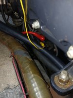
boat starter.jpg
 

ESGWheel

Chief Petty Officer
Joined
Aug 29, 2015
Messages
469
A ballast simply drops the voltage to the coil to abt 9VDC. This is supposed to extend both coil and point life. Supposedly there are 9V coils so running at 12 will mean it will run a little warmer and may shorten its life. A 12V coil running on 12 is fine. In either case you will get a hotter spark by feeding the coil 12V. So I think you are ok without ballast.

Jumping does work as you know but (1) that jumper cable looks a little small (wire gauge) for the current being drawn and (2) you already know you have to unhook it to shut down the engine but only hook back up when ready to start > do not leave it installed unless engine is running.

BUT need to get the issue squared away. It’s probably something simple and just need to tease it out. Do you have a multimeter or a 12VDC test light?
 

Bondo

Moderator
Staff member
Joined
Apr 17, 2002
Messages
70,953
I have a 1994 Glastron with a 5.7 GI Volvo Penta engine with electronic ignition, 2 barrel Holley carb with electric choke. Owned boat for about 6 weeks.

Boat worked fine the first few times I took it out, but then died when coming back to dock and would not restart.

I found that the coil was not getting power when the ignition was in the run position, but the coil did received power when the key ignition was fully turned to the start position. ( My first thought was bad ballast resistor ) I got the engine running again by running a jumper wire from the starter solenoid to the positive side of the coil. See picture below.

Here are my questions: The coil I have says to use an external resistor, but this boat has electronic ignition, ( meaning no points ). I thought the external resistor was only used on old point ignition system. So I'm confused on this topic.

More importantly the two questions I really have are: 1) is it safe to run a permanent wire from the starter to the positive side of the coil like I currently have the yellow jumper wire and 2) Since I'm not using an external resistor and I have electronic ignition, should I have purchase a different coil?
The coil I have right now is an SIE 18-5437 Ignition Coil

Right now everything sounds like it is running fine using the yellow jumper wire and I should just make that a permanent connection. But I am a little affraid, I just don't want to get out on the lake and find out that I fried the coil by sending it too much voltage.

You have any thoughts on this. I'm not an expert by any means and your thoughts would be greatly appreciated.

My gut feeling is the wiring in this boat has a ballast resistor or bad resistor wire that burnt out and that is why the coil wasn't getting any power. But for the life of me, I can not find any sort of resistor going to the coil.

Final note, I believe this boat originally had a 5.0 volvo penta engine in it, and somewhere along the line the engine was replaced with a 5.7. Nicely put together if that is the case.
Ayuh,...... Welcome Aboard,....... Yer problem sounds like a key switch issue, definitely not a coil issue,.......
With a meter, or test light, test the key switch, before you start blowin' money on anything else,.....
 

ESGWheel

Chief Petty Officer
Joined
Aug 29, 2015
Messages
469
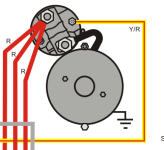
I was able to look more closely at your picture and now I am confused. Initially I thought when you said jumper wire fm the Starter Solenoid it was the battery cable lug (big red wire with boot). But you have it connected to what I would assume to be the terminal from the ign. switch, in other words wire that has the +12V ‘signal’ that from the ign. switch that causes the solenoid and thus the starter to activate. Since this wire is hot (+12VDC) ONLY when the key is turned to “Start” is why I am confused. See pic for typical wiring of these starters. The Yellow/Red Striped wire is the wire from the ign, switch and again only has +12VDC when key in “Start”.

Can you explain your situation in a little more detail. For example: do you need to disconnect the jumper to shut down the engine or do you simply turn the key off. If there another spade terminal on the back of the solenoid? Perhaps pulling aside those hoses and taking another pic and posting. Thanks.

Starter Solenoid.png
 

bcollida

Cadet
Joined
Sep 10, 2024
Messages
13
I was able to look more closely at your picture and now I am confused. Initially I thought when you said jumper wire fm the Starter Solenoid it was the battery cable lug (big red wire with boot). But you have it connected to what I would assume to be the terminal from the ign. switch, in other words wire that has the +12V ‘signal’ that from the ign. switch that causes the solenoid and thus the starter to activate. Since this wire is hot (+12VDC) ONLY when the key is turned to “Start” is why I am confused. See pic for typical wiring of these starters. The Yellow/Red Striped wire is the wire from the ign, switch and again only has +12VDC when key in “Start”.

Can you explain your situation in a little more detail. For example: do you need to disconnect the jumper to shut down the engine or do you simply turn the key off. If there another spade terminal on the back of the solenoid? Perhaps pulling aside those hoses and taking another pic and posting. Thanks.

View attachment 401015
Thanks for taking a look at this. I have the coil connected to the R terminal and everything is working fine. Starts right up, turns off with the key. Seems to work great. I ran a 12 gauge wire from the R terminal on the solenoid to an external coil resistor and then to the positive side of the coil.

I was looking for an easy to get to switched ( key on ) power source to power the coil. I'm sure there are other and probably better places where I could connect the positive side of the coil, but I don't know where to look.

So the real question is. Where would be the best place to connect the positive side of the coil? and thanks again in advance for your thoughts.
 

bcollida

Cadet
Joined
Sep 10, 2024
Messages
13
Thanks for taking a look at this. I have the coil connected to the R terminal and everything is working fine. Starts right up, turns off with the key. Seems to work great. I ran a 12 gauge wire from the R terminal on the solenoid to an external coil resistor and then to the positive side of the coil.

I was looking for an easy to get to switched ( key on ) power source to power the coil. I'm sure there are other and probably better places where I could connect the positive side of the coil, but I don't know where to look.

So the real question is. Where would be the best place to connect the positive side of the coil? and thanks again in advance for your thoughts.
My worst nightmare.

Thanks for taking a look at this. Here' s what I did. ( But there is more! see below) I ran a 12 gauge wire from the R terminal on the solenoid to an external coil resistor and then to the positive side of the coil. And I thought that fixed the problem. but I was wrong!

This morning, I unhooked the 12 gauge wire that I put on the coil. I did this to double check that my "fix" was working. I expected that the engine would NOT fire up. BUT CRAP. The engine fired up and ran perfectly without my "fix' in place. This means, I have an intermittent problem.

To restate the problem. the boat runs fine except, a couple of times now, at the end of the day, the boat died while at idle and getting the boat on the trailer. And I could not get it restarted.. With the key in the start position, the engine sounds like it will come to life, but as soon as the key goes to the run position the motor dies. And there is no spark coming from the coil.

Any thoughts?

I thought the best approach would be to find an alternative easy to get to switched ( key on ) power source to power the coil. but I don't know where to look.
 

ESGWheel

Chief Petty Officer
Joined
Aug 29, 2015
Messages
469
Here is what i just finished typing up to respond to your post no. 5.
===
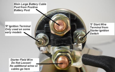
I had to reactivate some of my no longer used brain cells, plus did some google searching. Since you have an R Terminal your stater is made for older style points ign. No issue using that starter, just have an extra (unused) terminal – R. Well, until now. The R terminal is a fine place to pull power for the dist. as that is what it was made for. However, I am still confused as the R terminal should only have +12VDC during the start cycle i.e., when the starter is engaged. See below for a picture of a 4-terminal starter solenoid > yours should look like that. The fact that it works as you state makes me think there is something else wrong and it may reveal itself in ugly ways in the future. Not trying to scare, but anytime electrical things are not behaving as designed, it’s my experience things get worse.

To answer your direct question: yes, you can feed the coil off the R Terminal. However, I recommend placing a diode in the line to prevent back feeding during the start cycle. (A diode is a one-way check valve for electricity.) Recall the coil is getting power elsewhere when key is in Start. That power will now also be fed to the R Terminal. While probably not an issue, there is something funky going on with that R terminal coupled with the initial issue, so best be more cautious. Here is a link to one of those diodes specifically meat to do exactly what I am taking about. The reason it exists is for those older cars folks restore, they still use a modern starer that does not have a R terminal so need to simulate one. You will have to replace the large crimped on ring terminal with an appropriate connector.

With all that, it is my strong opinion that the question to be answered is “How to fix this issue back to the way it’s supposed to be?” Temp fixes are fine to get you thru the day or season, but long term best to find and fix the root cause. If you wish to pursue this, need at least a 12V test light, or better, a multimeter and this forum can help.
 

Attachments

  • 4 Terminal Starter Solenoid.png
    4 Terminal Starter Solenoid.png
    336.5 KB · Views: 2
Last edited:

ESGWheel

Chief Petty Officer
Joined
Aug 29, 2015
Messages
469
Bcollida,
Please take this the right way and I do not mean to offend > digest my post no. 7, reflect on it, and convince yourself this needs to be fixed the right way. No more permanent workarounds. Once you are in that space there are two choices (1) take it to a shop and (2) DIY. A DIY project can be fun as well as frustrating. But when accomplished that frustration turns into pride. And frankly it is probably something as simple as the ign. switch as Bondo was pointing out. If you commit to DIY, me and others on this forum will do our best to get you thru it and back on the water for fun in the sun!
 

Lou C

Supreme Mariner
Joined
Nov 10, 2002
Messages
12,652
Well what you need is a proper VP wiring diagram for your model, but lacking that, here's what I might do:
Remove the retainer for the igntion switch and see if you can rig it up to operate outside of the dashboard, so you can get to the terminals with a test light.
Then do some basic tests on the 3 terminals on the switch
"B" terminal (red wire) gets battery voltage when you turn on your battery switch
"I" terminal (purple wire) gets battery voltage when you turn the ignition switch to the 1st notch or the ignition on position.
"S" (yellow/red wire) terminal gets battery voltage when you turn the key to start.
So leave your "fix" off and the next time it doesn't start, check those 3 terminals on the ignition switch for power. If they all have power as they should, then it is possible your intermittent problem is in the big "cannon" connector, with 9 or so terminals in it, all the power from the dashboard harness goes through this connector to get to the ignition coil and starter circuits. The other place where you can have a problem is with the assist relay or starter solenoid, this is usually mounted near the engine and is connected directly to the big terminal on the starter and it receives the current from the key switch via the yellow/red wire. The reason for this is that it is to prevent voltage drop that would occur from running just that yellow/red wire from the key switch all the way back to the starter, instead the key switch energizes the solenoid which then sends power from the starter solenoid (direct connection to the battery) to the S terminal on the starter. That's how my old OMC is, I'm not sure if VP did things differently or not which is why you really need a wiring diagram.
Sometimes you have to pull that cannon plug a part, check all the terminals, clean up any oxidation, and put it back together with a hose clamp to keep it snug.
One year I had a no crank, no gauges issue and what it turned out to be was oxidation on the tabs in the fuse box that hold the glass fuses in place. Drove me crazy because the fuse had continuity and wasn't blown but the oxidation kept enough current from flowing to the ignition/cranking system.
 
Last edited:

Lou C

Supreme Mariner
Joined
Nov 10, 2002
Messages
12,652
PS if you can't find a VP wiring schematic for your engine, seeing as how you have a '94, that is the 1st year of the joint venture years between VP and OMC, so an OMC schematic for the same year, would likely be the same.
 

bcollida

Cadet
Joined
Sep 10, 2024
Messages
13
PS if you can't find a VP wiring schematic for your engine, seeing as how you have a '94, that is the 1st year of the joint venture years between VP and OMC, so an OMC schematic for the same year, would likely be the same.
Thanks for all your help. My auto mechanic guy is going to stop by this weekend. He says, " I think we should look at your ignition switch."
This has been very aggravating because I can not recreate fail situation. The boat runs great in the driveway!!!

Answer me this, with a multimeter connected positive lead to the R terminal on the starter solenoid and the negative lead to the battery, the meter reads 12 volts with the motor running and the key switch in the run position. I was expecting the multimeter to read 0 volts in this configuration( motor on and key in run position). So that seems wrong.

Also with a multimeter, positive lead on the positive side of the coil and negative lead on the negative side of the battery, motor off and key in run position, the meter reads 9 volts, which is what I expected.

Tomorrow I am going to check voltage at the coil with the motor on and the key in the run position. I believe I should still see 9 volts. But I suspect I am going to see 12 volts ( becuase I believe voltage is still going to the coil from the R terminal of the solenoid)

It's a learning experience. And thanks for the OMC / Volvo Penta merger info. in 1994. That's good to know, some of the things on this motor seem like an OMC set up ( like the raw water pickup )
I also have original sales paperwork from 1994 that shows the boat was sold with a 5.0 engine, but the engine and outdrive says 5.7 GI.

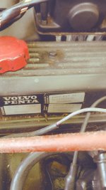
There are tags on the engine valve cover that say the following( I might have some of the numbers wrong)
Engine:
4110102051
3868067 5.7PMDA

Install Kit SX
4111503138
3868036

Outdrive
Drive SX 1 60
4112001556
386B068
 

Attachments

  • volvo engine.jpg
    volvo engine.jpg
    4.1 MB · Views: 2

Lou C

Supreme Mariner
Joined
Nov 10, 2002
Messages
12,652
Normally the R terminal is used on a points style ignition to provide full battery voltage to the coil only when the engine is cranking/starting, after the solenoid disengages the ignition coil is powered via the resistor wire that lowers the voltage to about 9 volts to keep the points from burning and make them last longer. Your engine has electronic ignition so I’m not sure why they would use the R terminal unless the type of electronic system they were using then also required lowered voltage to the coil.
Now I do know that Mercruiser used that terminal to power the electric fuel pump on carbed engines until the engine builds oil pressure and then the pump is powered off the oil pressure switch. But I don’t know if OMC or VP did it that way when they started using the later model GM Vortec engines that did not have a provision for a mechanical fuel pump…
 
Last edited:

ESGWheel

Chief Petty Officer
Joined
Aug 29, 2015
Messages
469
Intermittent problems, especially electrical ones, can be frustratingly hard to solve > its never there when you are looking as you are currently experiencing. While its always more comforting to “find it and fix it” sometimes other approaches are more expedient.

Here is how to go about both:
  • Determining root cause method 1: first need a suspected cause. In this case its highly probable it’s the ign. switch. And regardless, it’s a start and need to start somewhere. Then do a test as Lou suggests in post 9. With that test light on the “I” terminal and the key “ON” (so test light will light) jiggle the key, gently smack the assembly, etc. i.e., try it get that light to go out. If it does, then move over the test light to the “B” terminal (leave the key on but should not make a difference but want the same conditions) and jiggle, smack. If light stays on, it’s the switch. If light goes off, disconnect the wire from the B terminal and attach test light to the wire. Wiggle around the wire. If light goes out its in your wiring somewhere, if stays on, it’s the switch. Assuming light does not go off in either case it still could be the switch. The classic case of taking in your car for a noise that does not occur when the mechanic is driving it.
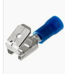
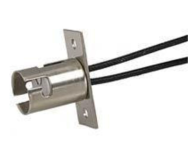
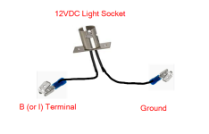
  • Determining root cause method 2: If above not definitive, the ign. switch can still be the cause. To create a truer “live” testing scenario make yourself up a couple of test lights from cheap components. Idea is to tie these into the ign. switch on both terminals B and I and with long enough leads so the test light bulbs are visible, perhaps draped over the steering column. Mark the B light so you know which is which. The components would consist of stackable spade terminals and a 12VDC light socket, like pictured below. Now go boating but have that jumper available. When the motor dies unexpectedly, look at the lights. If “B” light on and “I” light out > switch. If B light out > wiring problem.
I go into detail in the above for a couple of reasons: (1) to provide an easy method to live test you can use and (2) to highlight that troubleshooting is just a process of logical steps. In your mind’s eye, I am sure you can easily see that +12VDC power lost to either of these terminals would cause the issue and that this 2 bulb method would point to the problem.

And while it’s a simple enough test, its time consuming and you may need to use that jumper to get back home. But at least you know the situation.

What I would do: i.e., the easy method: put in a new switch. While this will not determine if it was the switch, so still need to carry the jumper. If no issues as time goes on, then you will know. This is called the ‘shotgun’ approach. Do not know the root cause but start changing parts to see if fixes. In case of an ign. switch, it’s just so cheap and easy, so expediency over knowing for sure.

Couple of other thoughts:
That this issue is not happening on the trailer leads to the idea its vibration or movement related. And this could easily be the ign. switch or a plug. Inspect your engine to helm plug (it’s a large 10 pin plug back in the engine compartment. Pull it apart and look for both corrosion and if any pin / spade is “pushed back” i.e., coming out of its hole. Fix all issues found. If need help with that, post questions.​

I’ll post separately on the R terminal.
 

Attachments

  • Stackable Connector.png
    Stackable Connector.png
    17.6 KB · Views: 1
  • light socket.png
    light socket.png
    122.2 KB · Views: 1
  • Test Light Rig.png
    Test Light Rig.png
    45.5 KB · Views: 1

bcollida

Cadet
Joined
Sep 10, 2024
Messages
13
Intermittent problems, especially electrical ones, can be frustratingly hard to solve > its never there when you are looking as you are currently experiencing. While its always more comforting to “find it and fix it” sometimes other approaches are more expedient.

Here is how to go about both:
  • Determining root cause method 1: first need a suspected cause. In this case its highly probable it’s the ign. switch. And regardless, it’s a start and need to start somewhere. Then do a test as Lou suggests in post 9. With that test light on the “I” terminal and the key “ON” (so test light will light) jiggle the key, gently smack the assembly, etc. i.e., try it get that light to go out. If it does, then move over the test light to the “B” terminal (leave the key on but should not make a difference but want the same conditions) and jiggle, smack. If light stays on, it’s the switch. If light goes off, disconnect the wire from the B terminal and attach test light to the wire. Wiggle around the wire. If light goes out its in your wiring somewhere, if stays on, it’s the switch. Assuming light does not go off in either case it still could be the switch. The classic case of taking in your car for a noise that does not occur when the mechanic is driving it.
  • Determining root cause method 2: If above not definitive, the ign. switch can still be the cause. To create a truer “live” testing scenario make yourself up a couple of test lights from cheap components. Idea is to tie these into the ign. switch on both terminals B and I and with long enough leads so the test light bulbs are visible, perhaps draped over the steering column. Mark the B light so you know which is which. The components would consist of stackable spade terminals and a 12VDC light socket, like pictured below. Now go boating but have that jumper available. When the motor dies unexpectedly, look at the lights. If “B” light on and “I” light out > switch. If B light out > wiring problem.
I go into detail in the above for a couple of reasons: (1) to provide an easy method to live test you can use and (2) to highlight that troubleshooting is just a process of logical steps. In your mind’s eye, I am sure you can easily see that +12VDC power lost to either of these terminals would cause the issue and that this 2 bulb method would point to the problem.

And while it’s a simple enough test, its time consuming and you may need to use that jumper to get back home. But at least you know the situation.

What I would do: i.e., the easy method: put in a new switch. While this will not determine if it was the switch, so still need to carry the jumper. If no issues as time goes on, then you will know. This is called the ‘shotgun’ approach. Do not know the root cause but start changing parts to see if fixes. In case of an ign. switch, it’s just so cheap and easy, so expediency over knowing for sure.

Couple of other thoughts:
That this issue is not happening on the trailer leads to the idea its vibration or movement related. And this could easily be the ign. switch or a plug. Inspect your engine to helm plug (it’s a large 10 pin plug back in the engine compartment. Pull it apart and look for both corrosion and if any pin / spade is “pushed back” i.e., coming out of its hole. Fix all issues found. If need help with that, post questions.​

I’ll post separately on the R terminal.
Awesome. thanks so much for the indepth response. I'm leaning towards buying a new switch and taking that potential issue off the table. I have a mechanic stopping by this weekend to take a look. His gut feel is the switch or a connector.

By the way, the two times if failed was when I was putting the boat back on the trailer and in both cases, I was doing some pretty aggressive, low speed steering. The ignition switch is mounted on the steering column
 
Last edited:

ESGWheel

Chief Petty Officer
Joined
Aug 29, 2015
Messages
469
R Terminal.
As stated in both posts 7 & 9, this terminal should only have +12VDC during the start cycle, specifically only when the starter solenoid is ‘kicked in.’ The movement of the solenoid causes the pinion gear on the starter motor to engage the engine AND closes a contact to cause R to have +12V. When solenoid retracts, contact open and R is dead. So, the solenoid is acting like a relay for the R Terminal.

The “why” is also in posts 7 & 9 with this added info: when the starter is engaged, the battery voltage drops to about 10V. Recognizing this, the ability to get full 9V to the coil via the ballast is a no go. Instead feed the coil full battery voltage during starting to ensure have enough juice to create a good spark.

What is going on? Here is my hypothesis based on what you are seeing on both the R Terminal (Constant +12VDC) and the Coil (+9VDC with Key On, Engine Off)

I think you do have a ballast resistor (hence the +9V) and there was some issue with the wiring / starter upon the new engine install such that they abandoned the R Terminal on the starter and wired up another way to get +12VDC to the coil when key in Start position. To know if starter or wiring issue, need to know if there is already a wire hooked onto Terminal R. Not your jumper but a ‘factory wire’ in the bundle of wires going to the starter. I had assumed it was naked based on the idea you were using it for the jumper, but perhaps it not.

If there is a ‘factory’ wire on R > remove it and test for voltage on both R and the wire separately with the Key on. Motor off (i.e. should not matter) but for giggles, do both motor running and not.
  • If have +12V on wire > possible wiring issue
  • If have +12V on R > starter solenoid issue
  • If both > multiple issues
Please post results.
 

ESGWheel

Chief Petty Officer
Joined
Aug 29, 2015
Messages
469
Some more while I am at it 😊
Here is a useful web site for parts look up, etc. > the VP web site at this link. Put in your engine serial no. and will get a selection of the various categories for your engine. Very helpful in figuring out part nos.

I did with your serial no. 4110102051 and it came back with 5.7GLPMDA which matches up with your sticker. Check it out.

And see this post no. 14 at this link for my go to places for getting parts.
 

Lou C

Supreme Mariner
Joined
Nov 10, 2002
Messages
12,652
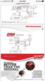
Also I did a bit of searching around, and if that engine has the same ignition system that both OMC and Volvo used in the '94 year, it is probably a Prestolite BID system which is basically an update of the old points distributor, keeping the centrifugal advance under the points plate but replacing the points with an electronic module (which of course, is NLA). I found some info on the CDI electronics site that suggest that the BID system also used a resistance wire (instead of a ballast resistor), same as the points system, not sure why so but that was all I could find out. So if in fact that engine has the BID system and not a later Delco EST, it should use the R terminal as it was used with the points distributors that came before. But since the engine was replaced, we don't know, so it would be good for the OP to verify just what ignition system is on the engine now.
 

bcollida

Cadet
Joined
Sep 10, 2024
Messages
13
Some more while I am at it 😊
Here is a useful web site for parts look up, etc. > the VP web site at this link. Put in your engine serial no. and will get a selection of the various categories for your engine. Very helpful in figuring out part nos.

I did with your serial no. 4110102051 and it came back with 5.7GLPMDA which matches up with your sticker. Check it out.

And see this post no. 14 at this link for my go to places for getting parts.
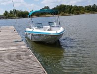
you guys are awesome. thanks so much for all the help and direction.. Its really a pretty nice boat for 30 years old
 

Attachments

  • carlyle.jpg
    carlyle.jpg
    1 MB · Views: 3
Top