Closed Cooling System on Port Engine Running Hot(ter)

HT32BSX115

Supreme Mariner
Joined
Dec 8, 2005
Messages
10,083
You might be able to find thicker gasket material....(I assume you're using sealant?)
 

tpenfield

Moderator
Staff member
Joined
Jul 18, 2011
Messages
17,873
OK, all set with the Starboard engine t-stat installation.

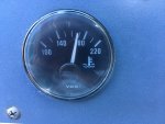
I ran the starboard engine up to temperature with the new t-stat (w/ 2 small by-pass holes). the engine settles in at about 168 per the gauge at idle speeds and no load.
IMG_8987.jpg


So that is the same as the port engine. We are 'apples-to-apples' at this point.

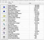
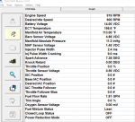
I also hooked up the Diacom to the engine to get some readings. Per the ECM (MEFI) the coolant temp is in the 158 F range, which is similar to what I was getting with the Port engine when I ran those test this summer. It looks like the helm gauges read about 10 degrees F higher than the ECM.

Here is the data from today. The engine RPM is a bit high, and I think it has to do with the intake plenum is not seating correctly, as I loosened it to get at the T-stat housing.

Starboard engine 10-12-2016.png

achris or Fun Times let me know any thoughts about the ECM data. I also have about 1 minute of recorded data if you would like that too.

Onto the Bravoitis . . .
 
Last edited:

HT32BSX115

Supreme Mariner
Joined
Dec 8, 2005
Messages
10,083
OK, all set with the Starboard engine t-stat installation.

I ran the starboard engine up to temperature with the new t-stat (w/ 2 small by-pass holes). the engine settles in at about 168 per the gauge at idle speeds and no load.


So that is the same as the port engine. We are 'apples-to-apples' at this point.
This is to say that both engines are now running at nearly the same temp with the "same" stats? Problem solved?
 

tpenfield

Moderator
Staff member
Joined
Jul 18, 2011
Messages
17,873
This is to say that both engines are now running at nearly the same temp with the "same" stats? Problem solved?

We don't know if the problem of the port engine is solved, but at least now both engine are coming up to temp at idle. I can re-run some of the other tests and do some of the other things suggested to see if there is a difference in how the engines cool. I think that may have been a confusing factor in terms of analyzing the ECM data, etc. Essentially, are the engines cooling differently because of the thermostats? perhaps, so making them essentially the same remedies that question.

Probably can do the IR Temp readings again and the sea water flow testing. I also suspect that even though the starboard engine now will run hotter because of the 'same' t-stat condition, that it will also cool better because of the de-scaling I just did on the Starboard Heat Exchanger.

Lot of variables in play . . . so I think my strategy is to make everything as it should be and use the 2 engines to compare.

My plan from here is to:

Do iron oxidation treatment on port engine

Run IR Temp surveys on both engines

FWIW - I'm going to run a full set of compression and cylinder leak tests

Fix Bravoitis on both engines (probably will do that in the Spring 2017 as part of the prep work).

Ideally, I'd like to get the temp gauges at the helm to be more consistent with the ECM temp readings, but I'm not sure there is a good way to do that. The fact that they are reading 10 degrees higher puts a bit of fear factor into the boat operation.
 
Last edited:

tpenfield

Moderator
Staff member
Joined
Jul 18, 2011
Messages
17,873
Oh, I just had a thought about the ECT temperature reading from the MEFI data vs. the helm gauge. VDO gauges use the Eropean sender standards for resistance and I'll bet the temp sender is the U.S. Standard, since it needs to be compatible with the MEFI.

Just not sure the exact ohm ranges of the U.S. Vs Euro for the temperature senders. I'll see what I can Google.
 

HT32BSX115

Supreme Mariner
Joined
Dec 8, 2005
Messages
10,083
.........................

Essentially, are the engines cooling differently because of the thermostats? perhaps, so making them essentially the same remedies that question.....................................

Probably can do the IR Temp readings again and the sea water flow testing.
Hmm.

Well, I can't remember if I said it before, but there *should* be a sea-water flow rate range (or minimum) where the T-stat would still be capable of maintaining the engine block temp at the desired temp (+/- slight differences)

So that even if one sea-water circuit was not flowing the *same* as the other, as long as it was "adequate" ..................it would still maintain the desired temp through the entire range of power output,

BOTH heat exchangers *should* provide more than enough excess heat transfer capability to do the job.

So maybe the engine temp differences were always the differences in the T-stats [and the "smoking-gun"]
 

tpenfield

Moderator
Staff member
Joined
Jul 18, 2011
Messages
17,873
The only thing is that the port engine used to run as cold as the starboard engine did. Towards the end of last season the port engine started running hotter. This season it ran 20 degrees hotter. So, something changed versus how it was initially. The work that I have done may have improved it, but the comparison is tougher if both engines do not come up to temperature.

I won't know for sure until next season. So the plan is to do the remaining work over the winter with hopes that the engines will run fine and in similar fashion.

I agree about the heat exchangers, they have excess capacity.
 

Fun Times

Moderator
Staff member
Joined
May 16, 2009
Messages
8,884
Ideally, I'd like to get the temp gauges at the helm to be more consistent with the ECM temp readings, but I'm not sure there is a good way to do that. The fact that they are reading 10 degrees higher puts a bit of fear factor into the boat operation.
Oh, I just had a thought about the ECT temperature reading from the MEFI data vs. the helm gauge. VDO gauges use the Eropean sender standards for resistance and I'll bet the temp sender is the U.S. Standard, since it needs to be compatible with the MEFI.

Just not sure the exact ohm ranges of the U.S. Vs Euro for the temperature senders. I'll see what I can Google.
The following link won't work here at iboats but search online "Troubleshooting Teleflex Water Temperature Gauges :Water Temperature System Accuracy?".

Good to see the engine temp is now within normal range, Now lets hope you can get them idle RPM's back down to normal too.;)
 

tpenfield

Moderator
Staff member
Joined
Jul 18, 2011
Messages
17,873
Thanks for the link Fun Times it is a good write-up. I have also done some research on the VDO senders. It seems that the temp senders start out at a very high resistance for low temperatures and go progressively lower resistance as the temp rises. From my research, it looks like the change in resistance vs change in temperature is not linear, which make adjusting the electrical circuit a bit tricky.

What I am not sure of at this point is how the MPI version of the temp senders differ from the traditional versions. My sender has 2 wires, and I'm not sure if it directly connects to the gauge, or if the gauge gets its connectivity through the MEFI. So, I should probably research that wiring as well.

For general purposes, I can assume anything 180 or below on those gauges is fine. I could try connecting a USA type of gauge to see what the temp reads.
 

alldodge

Moderator
Staff member
Joined
Mar 8, 2009
Messages
41,074
My sender has 2 wires,

The normal gauge sender has one wire (Tan), the warning switch (Blue/Tan pg 4E-8) the sounds the alarm has two wires. Your ohms readings are on page 4D-12. The US marine standard is 240-33 ohms
 

tpenfield

Moderator
Staff member
Joined
Jul 18, 2011
Messages
17,873
The temperature 2 senders . . . one has a tan wire (806490T), which I assume is the alarm :noidea:

the other sender (805218T) has a connector and the plug that connects to is has a yellow and an black wire. I assume that his one with 2 wires is the ECT?
 

tpenfield

Moderator
Staff member
Joined
Jul 18, 2011
Messages
17,873
Update . . .

I see that the ECT sensor (Yel/Blk) goes to the MEFI and the other sender does connect to the wiring harness that goes to the helm. So, it seems like separate sensors for the ECT for the MEFI and the gauge at the helm. It also seems like there is no separate overheat alarm (temperature switch)

Also, I thought the 240 - 33 ohm range was for the USA fuel senders, and not the temp senders?
 

alldodge

Moderator
Staff member
Joined
Mar 8, 2009
Messages
41,074
The alarm on your motor, which is similar to mine, is controlled by the ECM. In the post above I was using manual 23 which I should have used manual 16. On page 4F-6 (B-2) is the water temp gauge sender. The sender has one wire on it and goes straight to the gauge, to test remove, turn key ON and ground the lead, it should peg the gauge.

The ECT is read by the ECM on page 4F-7 (No 11) and has a yellow and a black wire. The alarm is sounded by the ECM buy applying a ground on the Tan wire coming from the MPI harness, which changes color to Tan/Blue and the engine harness connector (4 pin)

Edit: posted and then noticed your post
 

tpenfield

Moderator
Staff member
Joined
Jul 18, 2011
Messages
17,873
Yup, makes things easier. I can check the ohms of the sender (w tan wire) at various temperature to see if it is consistent with what VDO has for spec's etc.
 

alldodge

Moderator
Staff member
Joined
Mar 8, 2009
Messages
41,074
Ah..... yes and no I'm thinking. I know the difference between analog and digital, but the ECT sensor is a variable resistor just the same. Not knowing the inner workings of the MEFI-1, my guess is when the voltage changes to a preset value, is when a transistor would turn on and allow voltage to pass. Easy enough to do by designing the resistor between the base and emitter.

http://www.physlink.com/Education/AskExperts/ae430.cfm
 

tpenfield

Moderator
Staff member
Joined
Jul 18, 2011
Messages
17,873
I would assume that the MEFI does an analog to digital conversion of the sender's resistance value. One thing I noticed today as I did some more running of the engines, is that the ECT temp changes in increments, as if the MEFI has pre-set values to display and it is a matter of what the A/D conversion comes closest to.

Here is some of the data from my MEFI on the starboard engine . . . the top line (red) is the ECT value. Notice it changes in a step fashion, whereas the actual temperature obviously changes in a more gradual fashion.

ECTData1.png

Here is some data from the starboard engine. It behaved nicely today, and as it warmed up to the point of the thermostat opening, the ECT temp went down slightly, from the 157 F range to 154 F.

Stbd Engine 2016-10-15.png

The port engine was not having a good day. I re-connected the fitting and the hose at the transom assembly (where the Bravoitis is located) and drew the cooling water in through the outdrive. The other day, I had run the gravity feed hose straight to the sea water pump, and the engine ran at 157 F per the ECT.

Today it was taking the gravity feed water through the outdrive, the Bravoitis fitting, and the sea water strainer . . . It obviously does not like going that route . . . the water exiting the outdrive was visibly less in volume than the starboard engine and was quite hot (steaming). So, I think my issues lies within the outdrive, intake hose, fitting or sea water strainer.

Port Engine 2016-10-15-B.png

The temp gauge at the helm was reading about 180 F at this point.

Anyway, I have a good idea of where the port engine problem lies.
 

Attachments

  • ECTData1.png
    ECTData1.png
    177.7 KB · Views: 2

HT32BSX115

Supreme Mariner
Joined
Dec 8, 2005
Messages
10,083
the water exiting the outdrive was visibly less in volume than the starboard engine and was quite hot (steaming). So, I think my issues lies within the outdrive, intake hose, fitting or sea water strainer.

/////////////
Anyway, I have a good idea of where the port engine problem lies.
If you have "visibly" less raw water flow, your risers should of course be hotter and you may be at (or past) the limit of the excess heat exchanger transfer capability.

This may be the "smoking gun" all along....

"Fingers Crossed"!!
 

tpenfield

Moderator
Staff member
Joined
Jul 18, 2011
Messages
17,873
If you have "visibly" less raw water flow, your risers should of course be hotter and you may be at (or past) the limit of the excess heat exchanger transfer capability.

This may be the "smoking gun" all along....

"Fingers Crossed"!!

Yes, I'll be taking the elbows off over the winter, because the gasket & mating surfaces look like they need some attention. The elbows were part of the equation, when I ran the water directly to the sea water pump, so I think the intake is more suspect than the elbows. BUT the elbows (Stainless steel) will be looked at anyway.

I did a compression test today. Plugs look fine, both engines the same.. . . actually they look a bit on the rich side.

Compression numbers seem low, but the engine could just be getting tired. I did remember to open the throttle :)

Port
1=129
3=126
5=118
7=128

2=136
4=125
6=132
8=134

Starboard
1=125
3=123
5=118
7=120

2=125
4=121
6=124
8=127
 

HT32BSX115

Supreme Mariner
Joined
Dec 8, 2005
Messages
10,083
Port
1=129
3=126
5=118
7=128

2=136
4=125
6=132
8=134

Starboard
1=125
3=123
5=118
7=120

2=125
4=121
6=124
8=127

Those readings are pretty low! I did a compression check on my Franklin 6A-335B (aircraft engine) a couple of weeks ago and I got 120psi (and a leakdown of 78/80 with 76/80 being the lowest) it's a 7:1 engine though so 120 is good.

Shouldn't the 454's be around 150 or better? I see to remember measuring 155-160 when I had the OMG 460..........
 
Top