Charging a 24V system question

jrc1

Cadet
Thread starter
Joined
Mar 13, 2011
Messages
7
Currently have a 12/24 set up with 4 wires from the two batteries to the plug on the front panel, 4 prong plug into the trolling motor.
Bought a new 24v only motor. Was going to wire the batteries in series like I saw on another post
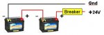
24VTrollerWiring.jpg

Got to find a female receptacle with two wires that will fit the Astro panel, current one has four screws in the corners of the receptacle.

Anyway my main question is about charging the batteries, my on board charger is currently connected to my 2 TM batteries and cranking battery. When I change the wiring scheme can I still continue to charge the same way or will I have to disconnect the wire from the positive of battery 1 to negative of battery 2 to charge them?:confused:

thanks,
JC
 

bassman284

Commander
Joined
Jun 24, 2006
Messages
2,840
Re: Charging a 24V system question

Well, I need Silvertip to weigh in here to verify, but I would say leave the onboard charger hookup the way it is, each bank of the charger charging one battery.
 

jrc1

Cadet
Thread starter
Joined
Mar 13, 2011
Messages
7
Re: Charging a 24V system question

Thanks, thought that might be the case and I would be leaving the charger connections the same, one bank per battery.
But do I need to disconnect the cable that is going from one battery's + to the other battery's - conenction before charging them?

Also, right now I have a 40A inline fuse on the + to the motor. Should that be OK or should I get a bigger fuse?
 

Barnacle_Bill

Admiral
Joined
Feb 8, 2004
Messages
6,469
Re: Charging a 24V system question

If you have a 3 bank charger and leads connected to the starting battery and one to each TM battery, you can leave it as is. You should be using 6 gauge wire from the batteries to the TM and a 60 amp fuse at the + post of the battery.
 

jrc1

Cadet
Thread starter
Joined
Mar 13, 2011
Messages
7
Re: Charging a 24V system question

Having a heck of a time finding a 60A inline fuse,
 

Silvertip

Honorary Supreme Mariner
Joined
Sep 22, 2003
Messages
28,772
Re: Charging a 24V system question

You don't need to change the plug or receptacle because there are only two wires. You simply use any two on the receptacle and plug. If nothing is connected to the other two terminals there will be no issue. You can leave the three charger outputs connected to each individual battery. If the charger has fully isolated grounds there will be no problem.
 

jrc1

Cadet
Thread starter
Joined
Mar 13, 2011
Messages
7
Re: Charging a 24V system question

Was trying to trace back the wires from the plug into the foot pedal on the old one. there are four wires into the receptacle but only three out of the plug into the pedal.
Each charger output connects to both the pos and neg battery posts, and there is a ground on the input power cord. Is that what you mean by fully isolated?
 

Silvertip

Honorary Supreme Mariner
Joined
Sep 22, 2003
Messages
28,772
Re: Charging a 24V system question

Absolutely not!!! Isolated grounds on the OUTPUT of the charger is what allows the charger to be connected to two batteries in a 24 volt series system. If you look at the diagram you posted, the jumper between the two batteries connects the POS post on one battery to the NEG on the other. Now think carefully!! If you connect separate charger outputs directly to the battery, don't you end up with the POSITIVE lead from the left side battery essentially connected to the NEGATIVE lead on the right side battery via the jumper between them?? Of course you do. Isolated grounds means the ground wires inside the charger are not common with each other and therefore cannot interact. If the grounds were common, it would be no different than simply touching the POS and NEG leads together and you know that makes sparks.

The reason there are three wires between the foot control and motor is that one is ground, one is 24 volts, and one is 12 volts. Selection is made on the foot control. The reason there are four wires from the batteries (two from each battery) is that this system uses a RUN/CHARGE switch on a panel on the bow to make the series connection, OR the series connection is done in the plug via a jumper. If you use that four terminal plug with the new wiring scheme you will need to remove that jumper. You just need to make sure the two terminals you use for the motor plug match up with the two terminals you use on the receptacle. Lastly -- DO NOT cut or remove the wires from the batteries that run up front. Use the ground wire on the battery on the left. Use the positive wire on the battery on the right. Disconnect the other two at the battery and tape the ends. Make a jumper to go between the two batteries. Up front, you can leave everything as it is except for the jumper in the plug and making sure the plug and receptacle connections match.
 

jrc1

Cadet
Thread starter
Joined
Mar 13, 2011
Messages
7
Re: Charging a 24V system question

I have no idea if the ground wires are isolated in the charger then, and there is no run/charge switch on the panel or pedal. How can I find out if they are isolated?

THe current wiring has a 40A inline fuse so that has to be changed to a 60A correct? I bought new 8 gauge wire to run new lines.
 

jrc1

Cadet
Thread starter
Joined
Mar 13, 2011
Messages
7
Re: Charging a 24V system question

How can I find out if the grounds are isolated?
 

Silvertip

Honorary Supreme Mariner
Joined
Sep 22, 2003
Messages
28,772
Re: Charging a 24V system question

Go to the manufacturers web site and look at the specs for the charger. If it says it can be used on 12 or 24 systems it will have isolated grounds. If you can't find any info, use an ohm meter to measure between the two grounds. If they are not isolated the meter will show very low resistance. If they are isolated the meter will show open circuit or very high resistance. Resistance is measured with power off so make sure the charger is unplugged when testing.
 

jrc1

Cadet
Thread starter
Joined
Mar 13, 2011
Messages
7
Re: Charging a 24V system question

So if it reads as an open circuit between any two of the negative leads it is isolated and good for a 24v system, correct?
 
Top