Bennett Trim Repair And Auto Pro Install

GA_Boater

Honorary Moderator Emeritus
Joined
May 24, 2011
Messages
49,038
I started needing fluids at 21 years old and today I still need to replenish daily. :rolleyes:
 

alldodge

Moderator
Staff member
Joined
Mar 8, 2009
Messages
42,344
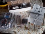
The parts came in, and the senders come with 2 sets of rods. The directions indicate to install with point end into the cylinder but does not say which to use. I'm going to assume it will be ones which will not interfere with screwing the hinge on. Will also need to drill a 5/16 hole for the wires. Will use a tad more 4200

Photo1333.jpg
 

alldodge

Moderator
Staff member
Joined
Mar 8, 2009
Messages
42,344
Well alrighty then :)

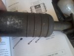
Removed the end caps (hinges) off both and was going to install new ones and the instructions did not say which of the rods to use, only that the pointy end goes to the bottom. Kit comes with 4 rods, 2 short and 2 a bit longer. Called Bennett and I need to use the long ones go with cylinders that have 4 rings, short go with the 3 ring cylinders.

Direction also says you need a 2 inch hole saw but believe this is a misprint, you don't need a hole saw of any size to install these if you alreadt have tabs installed. If you were installing new tabs, you might need a 1/2 to 9/16 drill for the hydraulic tube, or maybe a 1 inch hole saw if the line was connected directly to the hinge. Photo1340.jpg


Installed the hinges and was installing the brass tubes. First went in just like the old one, but the second had some issue trying to keep it straight. First thought I was cross threading, but kept looking at the threads and they looked clean. After a half dozen times of trying I started using some force to try an keep it straight. Managed to get it in but its still off 2 to 3 degrees from perpendicular. The pic doesn't show it very well but when holding with both hands it does.

Bennett suggested connect the cylinder to the pump and run it full down. Then let it sit for a while to see if there was a leak. Thought this would also be a good time to bleed and fill the cylinders. Just need to close off the tubes so oil doesn't come back out prior to using 4200 Photo1334.jpg


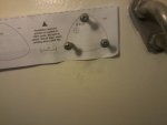
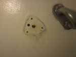
Next go to the boat and use the template to drill a 5/16 hole for the wires. Used the screws to hold template and drilled Photo1335.jpg
Photo1336.jpg
 

alldodge

Moderator
Staff member
Joined
Mar 8, 2009
Messages
42,344
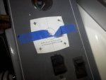
Taped the control template in position. Think this would work better using something clear (in my case) or even wax paper. This way I could see in reference to the holes already their. If I do this again, might try something like that.

Photo1337.jpg

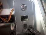
Then cut the center piece out using a hack saw blade

Photo1338.jpg

The screws on the back which hold the control are 2 inches or so, think I'll cut then shorter before finish installing

Photo1339.jpg
 

alldodge

Moderator
Staff member
Joined
Mar 8, 2009
Messages
42,344
I removed some things and managed to get barely enough room to get on the starboard side. I can reach the stern, and just be able to turn enough to get to the pump. This is not fun
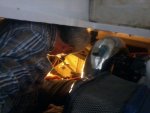
Photo1344.jpg

No complements to the pump fill spot, its about a 3/8 hole which was a bugger to get trans fluid in. At least the cap just sits on top the fill tube and part goes down in side. So removing was easy enough. My pump is so old you can no longer see thru the container in order to determine when the oil level is.

I used a gear lube bottle pour top and cut the top off a quart oil bottle to make a funnel small enough to use. At least the ATF poured n easy enough. Tried to use a small Philips screw drive as a dip stick, that didn't work very well. Was barely able to hold the funnel and pour. Filled the dang thing clear to the top.

Had the cylinders connected inside the boat and ran them up and down one by one. Left it full extended for a while and no leaks. So retracted both and there was ATF everywhere (overflow).
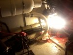
Photo1341.jpg

Got back in the hole and cleaned up the mess after removing the cylinders. Legs were barking at me, and after a short time they were saying if you don't get you butt up soon I might stop working. Well I didn't listen, and after a bit more of cleaning, I tried to get up and my one leg "Now What Did I Just Tell You?". So it took me some painful extra effort but I managed to claw my way back out. Circulation came back and I'm walking again

Used an empty oil bottle to pump a small amount of the fluid out. Then dumped fluid out of one cylinder by removing the hinge, then just poured the other out a bit. Hope this will bring the fluid level down enough to use without overflowing.

Cleaned the cylinders with Acetone, ruffed up the transom area with some sand paper, and clean with Acetone. Installed cylinders using 4200
 

alldodge

Moderator
Staff member
Joined
Mar 8, 2009
Messages
42,344
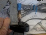
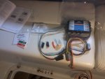
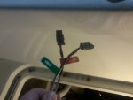
Was running the port wires over to starboard side, then needed to put the connectors on the wire ends. Easy enough, just slide them in the connector until they lock. They come with tabs to mark the cables and looks like lock pieces (orange things) to keep the connectors from coming loose. They are snap lock connectors so not to sure if they are needed, but will use them.

EDIT: The orange things are part of the connector and need to be used after wires are inserted, see future posting
Photo1347.jpg
Photo1348.jpg


Hey Bennett you need to work on your instructions.

The cylinder senders come with a one page instruction sheet, connectors, labels and rods. The instructions say go to page 7, 8 and 9 for how to connect. Well those pages say nothing about how to do it. Since this is a coil of wire and it should make no difference how the Red and Black wires are connected to the box, I just pushed them in. There is no mention of the lock tabs

The ATP book says to find a location for full time 12V to connect to the Orange wire (used to auto retract when motor is shut off), and for 12V Purple wire to ignition power. Both the Orange and Purple (4 feet) I'm thinking I would put it up close to the helm, but away from the compass. Problem here is the cylinder wires are only about 12 feet long.

The ATP has a built in gyro, accelerometer and electronic compass and statement says it can be mounted in any orientation. With the helm cable being 25 feet long, it looks like I will be placing it in the engine room. What makes matters worst the cable that connects the pump to the ATP (in my case) is only about 4 feet, so now it will probably be over on the starboard side.

I put some electrical tape behind the connector to cover and help support the wires. Should have used heat shrink but thought the wires would go inside the connectors like the others
 
Last edited:

Tabman

iboats.com Partner
Joined
Feb 21, 2002
Messages
566
Forwarding to the guys that write the instructions.

Tom
Bennett Marine
 

alldodge

Moderator
Staff member
Joined
Mar 8, 2009
Messages
42,344
Back to the orange things:
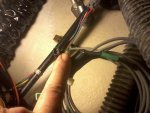
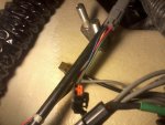
The orange pieces are part of the Port and Starboard trim connectors. Thought they looked weird but didn't dawn on me until after I was done and looking at left over parts. I then noticed the same orange pieces inside the connectors. Pulled the connector apart, straightened the pin (was at an angle, and then it slid right in.

Photo1353.jpg

Orange piece installed

Photo1354.jpg
 

alldodge

Moderator
Staff member
Joined
Mar 8, 2009
Messages
42,344
Installed the ATP unit next to the trim pump. This was the easiest place with the limited cord. The cord is about 2 feet and was glad my unit needed the adapter connecter which gave me another foot, would suggest at least 4 feet. If the motor was out, I would have placed it closer to the pump unit.

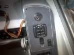
Connected the control panel, and wired the Orange and Black to the buss bar behind the helm. This buss bar made it easy for constant power but also come from the house bat and not the start bat. This just means both need to be ON for unit to function. Only time I turn the switches OFF is in winter storage. Might change later but for right now glad this is done.

Blurry pic but oh well. Connected the purple wire to the purple going to the gauges

Photo1350.jpg

Jacked the boat off the trailer and tied the cylinders away from the tabs for initial calabration. The up down worked as instruction stated, do notice if your cylinders have a lot of air in them like mine did, you might have to try the cal twice like I did to have it work.

Photo1352.jpg

The FAV lights will continue to flash until boat is in the water and it is orientated with the unit, same goes for the 4 corner amber lights will stay ON. I just turn the switches OFF and will wait for spring to finish

Last notes:
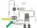
The pic below is my design, the first layout in the book shows one like it but does not have sensors for the cylinders. I have made the connections for clarity. Also note the ATP Helm control cables comes from the left side bottom connection and the cable is about 3 feet long. The cable coming from the bottom left is used by Bennett to program the unit and is about 6 inches long.

trim.jpg
 

Old Ironmaker

Captain
Joined
Dec 28, 2015
Messages
3,050
Wow, from going to a fix for a small hydraulic leak for a trim cylinder in July to going to a new trim control system in November. I read through these threads where I don't have a clue of to learn something new. I have always dreamt of having a nice big barge with an I/O. What I have really learned here is to stick to my 19 foot tinny with the outboards unless I go back to work or win the Lottery and pay the "guy" to do what you guys do in your sleep. I know just enough mechanical to be dangerous and just enough electrical to fry myself from a 12V battery. I did pick up a few simple tricks I can use in the future. When I first bought my 1st real boat, my previous was a Sears car top, all I knew was the pointy end was the front and the steering wheel was on the wrong side. Thanks for the read. You guys are good.

Johnny D.
 

GA_Boater

Honorary Moderator Emeritus
Joined
May 24, 2011
Messages
49,038
Wow, from going to a fix for a small hydraulic leak for a trim cylinder in July to going to a new trim control system in November. I read through these threads where I don't have a clue of to learn something new.

Johnny D.

Sure was a change in direction! I also read a lot of threads and it's better than staying at a Holiday Inn Express. :D

Nice job putting this all together, AD. :thumb: Do we have to wait for Spring for the final chapter? :blue: :smile:
 

alldodge

Moderator
Staff member
Joined
Mar 8, 2009
Messages
42,344
Do we have to wait for Spring for the final chapter? :blue: :smile:

Yes, seems so. The only way to know if everything works as it should is after the ATP controller has been orientated to the boat.

My only thought right now is what happens IF the fluid level is to high. I have no way of knowing if it is or not
 

mr300z87

Senior Chief Petty Officer
Joined
Sep 15, 2010
Messages
694
Nice work AD, I think I will just repair my leak although I am curious how the system functions. My Sea Ray has no issues getting on plane so the tabs are used mainly for fixing a list at cruise speeds do mostly to the winds at my beam, and or load. Will the system help with this too?
 

alldodge

Moderator
Staff member
Joined
Mar 8, 2009
Messages
42,344
Thanks

Bennett tabs use hydraulic pressure to extend the tabs, and 80 pound springs in each cylinder to retract them. The pump runs it both directions but really does not pump fluid back out.

I don't use tabs to get up only to keep us level. After breaking one of the hinges I looked into auto retract. Thinking the crack happened right after a bunch of friends came down which caused me to use more tab down to keep level. I did not retract the tabs before putting on the lift, so think this may have caused the issue.

You can add auto retract to the system for much less, just need sensors (about $60) and auto retract (about $50) unit. I went with the full auto tabs so it will automatically keep the boat level as folks move around and if I have more folks on then normal. Kind of like cruise control for a boat.

They can also be disabled or enabled with pressing one button. Then when I shut the motor down they also retract full up
 
Top