achris
More fish than mountain goat
- Joined
- May 19, 2004
- Messages
- 27,468


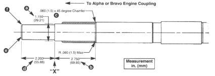
Nice idea, although I've never had a problem just eyeballing it.Some members have noted using a pipe that has an outside 1 1/8" diameter plugged into the coupler and sticking through the gimbal bearing to see the angles. The pipe will give you some clues as to exactly where the engine is.
But.... yer special.Nice idea, although I've never had a problem just eyeballing it.
Apart from forcing the engine to hard to starboard before drilling for the mounting coach screws (some call 'lag bolts'), about the only thing that can cause a port/starboard misalignment is an uneven thickness transom.I was actually using a 1" pipe which showed the misalignment to port.
I hear ya...I really hope that I don't have to go down that rabbit hole.Apart from forcing the engine to hard to starboard before drilling for the mounting coach screws (some call 'lag bolts'), about the only thing that can cause a port/starboard misalignment is an uneven thickness transom.
Chris......
Using a small LED torch you should be able to see the splines quite easily. And if the drive came off without issue, then there shouldn't have been anything to cause any damage.Just curious but what are the chances that the coupler splines were damaged somehow so that it would prevent the shaft from sliding in?
That's the conclusion I reached on mine. Could never get the alignment quite right, and the issue persisted on the new engine. Presumably it's been like that for 36 years, and at least 13.If you have a left/right alignment issue, then it could be caused by an uneven transom thickness. If the alignment was correct in the past, then something (bad) has happened.
BTW, all we know so far is that the drive is an Alpha One Gen II. Any chance of letting us in on the engine and it's year?
Chris.....

If you have the style of gimbal bearing install tool that uses the alignment tool with a hole in it to hold a disc pushing the gimbal you may have been pounding on the splines.Update:
My issue ended up being squared off splines at the coupler. Drive would go in as far as the coupler and stop there. I was able to get a small triangular file way in there to reach the splines and take off the burrs. I'm assuming I damaged it while installing the gimbal bearing somehow. Anyway, the drive goes in no problems now.
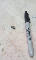
So in the process of cleaning out the splines (old grease, filings, etc) I found a little piece of steel (had some black paint on one end) lodged up against the flywheel deep inside the coupler. Any idea what it was from?
View attachment 365445
Yup, you're right, I think that's exactly what may have flatted the splines. Excellent suggestion! I'll have to make sure I shim the install tool next time.If you have the style of gimbal bearing install tool that uses the alignment tool with a hole in it to hold a disc pushing the gimbal you may have been pounding on the splines.
metal piece dont thing it is ring gear or starter gear tooth ?..
I have used a 1” wooden dowel around the outer race and also a 3” pvc sch 40 pipe piece works okYup, you're right, I think that's exactly what may have flatted the splines. Excellent suggestion! I'll have to make sure I shim the install tool next time.
Ive never used it always made my own drivers out of material i already had to hit outer race.Scott06 you say this install tooll disc mounted on the tool is a wrong one??