1978 Islander 22 I/O

IslandExplorer

Chief Petty Officer
Joined
Oct 21, 2019
Messages
460
What a cool project, love those Islanders! And man I wish I could see what you're working with. You need to grab yourself an image hosting app or something if you can stand it so we can see this project unfold! I'm using free imgur currently, it's a pain but it works for now..

That engine swap will be an awesome upgrade and agree that you definitely don't want to be underpowered playing out on big water. If you had the engine hanging sort of in place it could help with your engine mount planning maybe. Otherwise designing in extra adjustability, if possible, might be nice. I think with your careful measurements, and the play in the mounts providing adjustment, you'll do fine. How many HP is that model 4.3 you've got? I didn't realize some w 4bbl went all the way into the 225 range, impressive little motor!
 

66Holiday924

Chief Petty Officer
Joined
Aug 21, 2017
Messages
576
What a cool project, love those Islanders! And man I wish I could see what you're working with. You need to grab yourself an image hosting app or something if you can stand it so we can see this project unfold!
Thank you for your interest! It's good to know I'm not talking to myself! I have faith in iBoats. I'm waiting for them to resolve the issue and then I'll do a photo dump. I don't want to get into 3rd party photo sites and creating more accounts.
designing in extra adjustability, if possible, might be nice. I think with your careful measurements, and the play in the mounts providing adjustment, you'll do fine. How many HP is that model 4.3 you've got? I didn't realize some
My engine is a 1992, 4.3 MerCruiser, 4BBL and is rated at 180hp (per MerCruiser). I don't have an engine hoist, so hanging it in place isn't really an option for me. I spent a couple hours double checking my measurements yesterday. I went through pictures I had taken of the donor boat when I grabbed those measurements, I compared them to the engine on the pallet, and I laid it all out on the Islander. I think I am about as confident as I can be based on measurements. Nonetheless, I have a plan to build them such that they can be adjusted pretty easily.
 

IslandExplorer

Chief Petty Officer
Joined
Oct 21, 2019
Messages
460
I hear ya, more accts is another headache to deal with. 180 HP will be a great upgrade, that engine will just be purring along without strain! I wonder what the weight difference is from the 4cyl to V6. I'd guess that 4.3 is really light for what it is putting out. Engine block I'd think would be lighter than the I6 for the Mercruiser 165 you mentioned previously and that they commonly put in the Islanders and Chieftains but maybe the exhaust equals it out? If you happen to already know the weight comparison #'s I'd be interested.
 

66Holiday924

Chief Petty Officer
Joined
Aug 21, 2017
Messages
576
I wonder what the weight difference is from the 4cyl to V6. I'd guess that 4.3 is really light for what it is putting out.

Per MerCruiser, my 4.3L weighs 763lbs, the drive is 85lbs, and the transom assembly is 80lbs

The 3.0L Weighs 500ish and it would have the same drive and transom, so there's about a 250lb. difference.

I don't know what the straight six 165 weighs. I know they were optional in these boats. The weight is probably in the ballpark of the 6 cylinder I'm going to install.

Considering the engine weight differences played a part in my decision to relocate my batteries up by the helm. That'll be 140-160lbs shifted from the rear.
 

IslandExplorer

Chief Petty Officer
Joined
Oct 21, 2019
Messages
460
Wow, that's not that much more really, like just having an extra passenger in the back. The battery relocation should make a huge difference. These boats have so little weight up front so adding the batteries up there seems to have a more dramatic effect than average. I did that with the 2 house batteries on my old Starchief and it was a night and day difference. Planed out super easy and would maintain plane at much lower speeds after that. The only thing that sucked about it really was buying all the expensive damn cable!
How many batteries are you running in this rig? 2 deep cycle, 1 start?
 

66Holiday924

Chief Petty Officer
Joined
Aug 21, 2017
Messages
576
How many batteries are you running in this rig? 2 deep cycle, 1 start?
As of right now, I plan on running two 27 deep cycle marine batteries, but as I've mentioned, I've never set up a fishing boat so that may change. I also haven't looked into what MerCruiser says with this engine.

I just secured the plywood layer to my Coosa transom. I used 9 -316 SS, 1" lags and washers (aggressive threading on the lags). This will hold it in place and keep the edges down just fine until I start thru-hull mounting stuff. I tried to keep them out on the edges where they shouldn't be in the way, but if a lag is in the way of something down the road, I'll just move it.

Turning my focus on transom savers and building my engine mount. I know I'm going to have some deep cuts to do on my transom mount. I don't even see a table saw for sale at the big box stores that can cut as deep as I need, so, instead of spending hundreds of dollars on a saw, I'm going to go have a conversation with the Amish and see if I can pay them to make a couple cuts for me.
 

66Holiday924

Chief Petty Officer
Joined
Aug 21, 2017
Messages
576
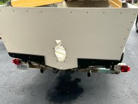
Yesterday I got my custom transom savers cutout and installed. The admiral actually helped, and we had fun working on it together. I went with black king's starboard because I plan on the bottom of this boat being painted with black anti-fouling paint.

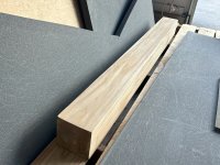
A couple days ago I started work on my new stringer engine mounts. They are going to be coosa and teak. Their overall height (based on my best measurements) will be 8-1/4". My plan is for the bottom 3-1/2" to be laminated coosa I have left over from my transom, and the 5x5 teak timber to be the top 4-3/4". The coosa, which does not rot, on the bottom, will be a protective layer at the bottom, in the bilge, and it will be what gets wet, if/when there is bilge water. The Teak timber on top will provide a competent surface for the engine mounts to be bolted to, and for the stringers to be bolted through, so they can be mounted to the hull of the boat (via aluminum brackets & 316 SS hardaware). The coosa layer has currently been laminated together with Total Boat's 5:1 epoxy & silica thickener, mayonnaise consistency as described on the two YouTube videos that made me an expert šŸ˜‚. The coosa and the teak layers will be mechanically joined by 3, 1/2", Grade 8 steel through bolts.

I've seen in the past where marine-ply was used for stringers. For my design the stringers will have to be screwed and bolted through from all sides, so I went with the timber instead of ply. The holding strength of ply is fantastic, unless you're going through the sides, which is necessary with my design.

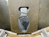
Currently, I'm having the Gimbal Assembly installed while I work on the engine mounts. I want the gimbal assembly in because the stringers will tie into the transom via aluminum brackets, and I want to make sure they don't interfere with it. So best to have that in first.
 

IslandExplorer

Chief Petty Officer
Joined
Oct 21, 2019
Messages
460
Sounds like some nice progress you've made. It's esp great to get some things done with the admirals help! I like your idea with the rot proof layer on the bottom and teak on top- that sounds like it'll be super solid and last practically forever. That little bit of extra mass should also make for some nice vibration absorption I bet vs a more hollow aluminum structure.
 

66Holiday924

Chief Petty Officer
Joined
Aug 21, 2017
Messages
576
I was kind of down yesterday, prepping for a colonoscopy (sorry if that's TMI), so I decided to spend the day thinking about how I want to outfit the boat for fishing, and the electrical system. For me, for my comfort taking the boat out it comes down to three separate onboard electrical systems. Safety above all, this is meant to be a Great Lakes fishing boat, you have to be able to start the main engine. I'd like to be able to listen to the radio while fishing, and I need to run my fishing equipment. So, my plan, is to run Blue Sea System's "Add a Battery" system for my starting battery and my house battery. In addition to that, as recommended by Cannon, I plan on running my downriggers off their own dedicated batteries.

Blue Seas's Add a Battery Kit includes a relay, and once the battery switch is on and the boat is running, it automatically alternates between charging the starter battery and the house battery as needed. In addition to that, on that part of the system, I'm going to wire it so the kicker motor keeps the house battery charged while I'm trolling, listening to the radio, running my navigation equipment.

The other system is the three downriggers I plan on running. I think this boat will have three, Port, Port aft, and starboard. I'm going for the Cannon Magnum 10's. Cannon recommends that they be on their own dedicated battery, two per, battery. So, I'm going to set that system up completely independent of the primary electrical system which is critical to the function of the boat. I'm going to wire it all up, and have those batteries connected to a NOCO Battery Charger that I can plug into through a thru-hull fitting (similar to a shore power port), so it will look like my boat has shore power, but it's just charging the downrigger batteries between trips.

So, I guess four batteries, two for the operation of the boat and two for my downriggers, as recommended by cannon. The plan will be to plug it in at home the night before fishing trips until I get a slip that has shore power someday. Those chargers are nice, you can leave them plugged in indefinitely and they alert you when the batteries are going bad.

As I've said, I've never set-up a fishing boat. I've been on plenty though. This seems like overkill, but I think it'll be a clean system to keep the downriggers separate from everything else. I do not want to be on Lake Michigan and need a tow, ever. Anyway feel free to let me know what you think.
 

IslandExplorer

Chief Petty Officer
Joined
Oct 21, 2019
Messages
460
That sounds really heavy duty and I'm sure you'd have no problems with the downriggers being underpowered or problems with reliability or anything.
Here are my opinions/ideas if interested:
Personally, I'd feel safe losing a battery from that setup. You could run one nice big battery for all 3 riggers I'd think, esp if they only are run intermittently or 1 at a time, but maybe I'm wrong. +1 house, +1 start. You could have the engine on the standalone start battery, have a separate house battery, and your separate rigger battery. Put a VSR (voltage sensing relay) in so the start battery is totally protected, engine charges start battery to full 1st, then the other(s) by design. And hook up the kicker to the down rigger batt. You could run the rigger battery dead and house battery dead with radio and still have start battery 100% charged and isolated.

This would make for a 3 battery system which, if full size batteries, is a pretty damn stout system in a boat that size w single main engine imo.

But if weight is no penalty- then the more batteries the merrier/better for ultimate reliability. Nothing wrong with 4, esp if you feel safer that way. The great lakes are easily as dangerous as the sea so it's understandable that you'd want to feel extra prepared out there. That's sweet that your kicker has a charging system- wish mine did!
 

66Holiday924

Chief Petty Officer
Joined
Aug 21, 2017
Messages
576
I appreciate the feedback for sure. It's good to know that I'm not completely off with what I've come up with.

I'd feel safe losing a battery from that setup. You could run one nice big battery for all 3 riggers I'd think, esp if they only are run intermittently or 1 at a time, but maybe I'm wrong. +1 house, +1 start.
I thought really hard about putting the downriggers on a Group 31 and doing just that. There were a couple reasons I decided on the four battery instead.
1. Weight distribution - Think it'll be easier to balance the boat and keep everything symmetric with an even number of batteries.
2. Cannon's Recommendation - I'm already interested in keeping the number even, having it comply with Cannon recommendations doesn't hurt.
3. I was thinking, this would mean one rigger will be on its own battery. So it'll almost be like having an emergency battery onboard. If I drain something, I should be able to hook this battery up and go.

But if weight is no penalty- then the more batteries the merrier/better for ultimate reliability.
This Boat is rated for 8 People, it's going to be set up to fish 4 maximum. So, I have some weight to play with. Setting the 4 - 70lb batteries up by the helm should make it ride even better.
That's sweet that your kicker has a charging system- wish mine did!
I don't have a kicker yet. I want a 9.9 Yamaha. They say those things are great. It puts out 6AMP at WOT. So, it doesn't really offer a lot, but it can be hooked up to help charge a battery. I see a lot of people say that they don't keep up with keeping their downrigger batteries charged. I figure, it, on the house battery ought to keep me going with the radio and fish finder. Then the main will charge it via the Blue Sea Add a Battery Kit on the way in. People say they put different props on them, to get more RPM's so they charge a little better while they are trolling, but they can't keep up with the heavier stuff. Those electric downriggers draw 25-30AMPS.

I spent a day thinking about it. I like the idea of keeping the downriggers off the main system for the boat entirely. I think it's cleaner Someday when that stuff is outdated it'll make it a lot easier to swap out or remove entirely for sale or something.

They say some of the newer Mercury kickers put out 15Amps or so.
 

IslandExplorer

Chief Petty Officer
Joined
Oct 21, 2019
Messages
460
I also only plan on having less than the rated capacity of ppl aboard so my boat gaining a little weight didn't matter to me either. These aluminum boats are so light to start with, I see it as a real plus for those into modifying/adding other capacities.

That's a good point with the single rigger battery. It will be a nice backup!

It's too bad kicker motors don't commonly put out much more than a couple amps... 15amp is definitely an improvement but 20+ would be really nice when you have a lot of accessories. Wonder if a good alternator shop could boost the output of the coils on one... Not much risk since it wouldn't be the primary charging system. šŸ¤·ā€ā™‚ļø I'd love it if my kicker was like a little generator too, putting some significant amps out.
 

66Holiday924

Chief Petty Officer
Joined
Aug 21, 2017
Messages
576
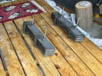
Today I cut my stringers. My original idea was to try to find somebody with a nice big saw to help me because the teak is 5"x5" and my laminated coosa base is 5"x3.5", instead I ended up making two passes for each cut with a table saw. I have to say, I did a pretty good job today. I'm giving myself an A. I now have two 8.5" tall, 28.75" Long, 5" wide, rectangular polygons. Each has a 3.5" Coosa base and a 5" teak timber top. the backs are angled so they will ride up my transom.

Right now, they are clamped together exactly how I want them, ready to be drilled for the three 1/2", Grade 8, Bolts that are going to mechanically join them. Before I can drill it, I have a surprisingly small amount of sanding to do for what this is, and the tools I had to make it.

They get drilled, then I shave a triangular prism off of the coosa base such that they will match the contour of the boat ribs that they will rest on, and the tops will sit flat. All together, they each span three ribs, so a nice distribution of weight.

I'm going to go ahead and give myself another pat on the back for the 5:1 w/silica base epoxy I mixed up to laminate the coosa the other day. It's as good as it could be. I was curious so I tried splitting some of the scraps that I had laminated and the coosa board failed before my mix did. So, it's bound together stronger than the coosa. Mayonnaise consistency! Basically, slowly mix in the silica until you're mixing and it kind of holds shape. They all say there is no science to it, it's an art.
 

IslandExplorer

Chief Petty Officer
Joined
Oct 21, 2019
Messages
460
Sounds like you've been kicking ass on this. Really wish we could see it though!!
The silica base epoxy mixing and application is an art. But beware, bc without proper ventilation or a mask- it could become a lifestyle. šŸ˜†
So with the notching you described, are the supports resting against the hull skin at the bottom or just notched around the 3 ribs a bit? Curious how you are connecting it to the hull and how the part that rides up the transom will be attached.
 

66Holiday924

Chief Petty Officer
Joined
Aug 21, 2017
Messages
576
These pictures go with posts 60 & 62 painting the transom skin.
 

Attachments

  • 20240730_171909879_iOS.jpg
    5.6 MB · Views: 3
  • 20240730_171923718_iOS.jpg
    4.6 MB · Views: 4
  • 20240730_172125889_iOS.jpg
    2.8 MB · Views: 2
  • 20240730_201916674_iOS.jpg
    6 MB · Views: 2
  • 20240730_201932911_iOS.jpg
    3.7 MB · Views: 2
  • 20240806_201832694_iOS.jpg
    4.2 MB · Views: 2
  • 20240806_201849815_iOS.jpg
    3.5 MB · Views: 3
  • 20240806_201915724_iOS.jpg
    4 MB · Views: 2

66Holiday924

Chief Petty Officer
Joined
Aug 21, 2017
Messages
576
These are the pictures that go with building the horse collar, transom installation.
 

Attachments

  • 20240806_180520218_iOS.jpg
    5.3 MB · Views: 1
  • 20240806_181640994_iOS.jpg
    5.7 MB · Views: 0
  • 20240806_200442729_iOS.jpg
    6.1 MB · Views: 0
  • 20240806_224900687_iOS.jpg
    5.6 MB · Views: 1
  • 20240813_222538624_iOS.jpg
    4.7 MB · Views: 0
  • 20240813_222713402_iOS.jpg
    3.1 MB · Views: 0
  • 20240823_135451711_iOS.jpg
    5.5 MB · Views: 1
  • 20240823_135533205_iOS.jpg
    20240823_135533205_iOS.jpg
    3.4 MB · Views: 5

66Holiday924

Chief Petty Officer
Joined
Aug 21, 2017
Messages
576
These pictures go with building the plywood layer to my transom from the ply template I used to make the coosa transom.
 

Attachments

  • 20240814_125656436_iOS.jpg
    3.9 MB · Views: 1
  • 20240814_153357340_iOS.jpg
    3.9 MB · Views: 1

66Holiday924

Chief Petty Officer
Joined
Aug 21, 2017
Messages
576
3/4", custom cut, King's Starboard transom savers the admiral and I installed. I placed the bolts on the ends where you wouldn't put a transducer, and the middle is in line with the strakes where there would be too much disturbance.
 

Attachments

  • 20240906_145359511_iOS.jpg
    20240906_145359511_iOS.jpg
    2.5 MB · Views: 7

66Holiday924

Chief Petty Officer
Joined
Aug 21, 2017
Messages
576
Building my stringers. The base is 3.5" laminated coosa, and the top is going to be 5"x5" teak timber. I did not laminate the coosa to the timbers. They will be joined mechanically with 1/2", Grade 8, steel through bolts. The bolts will be put in through the bottom so then, after they are installed, it will be possible to slide the teak off of the bolts/studs for easy removal.
 

Attachments

  • 20240809_192705763_iOS.jpg
    20240809_192705763_iOS.jpg
    3 MB · Views: 2
  • 20240825_143243677_iOS.jpg
    4.3 MB · Views: 1
  • 20240825_143259925_iOS.jpg
    4.2 MB · Views: 1
  • 20240825_143621703_iOS.jpg
    20240825_143621703_iOS.jpg
    915.3 KB · Views: 2
  • 20240904_163631512_iOS.jpg
    4.4 MB · Views: 1
  • 20240904_180942373_iOS.jpg
    20240904_180942373_iOS.jpg
    2.9 MB · Views: 2
  • 20240910_145740994_iOS.jpg
    4.6 MB · Views: 1
  • 20240910_183808781_iOS.jpg
    6.2 MB · Views: 2

66Holiday924

Chief Petty Officer
Joined
Aug 21, 2017
Messages
576
Curious how you are connecting it to the hull and how the part that rides up the transom will be attached.
I have to finish cutting out my stringers. I have to cut away a triangular prism from the coosa, so it will match the contour of the bottom of the boat/ribs.

They are going to rest on three ribs. I plan on using a drum sanding bit on my drill to get them to kind of hug the ribs.

Each one is going to be mechanically attached through the hull of the boat via two aluminum brackets. The brackets will be attached to the teak with 3/8" stainless lags and through the hull with 3/8" thru-bolts. Additionally, each stringer has another bracket that joins the back of the stringer to the transom which gets secured with 3/8" stainless lags.

So, a total of three brackets per stringer, two on the inboard side, attaching to the teak and through the bottom of the boat. One on the back tying into the transom. all 3/8 stainless hardware. Each bracket has two lags into the teak and two through bolts tying into the hull of the boat or transom.

With my last post, the pictures should be up-to-date. Tomorrow I'm going to do a little sanding on the stringers to get them cleaned up and down to their final size so I can mark them accurately to finish building and install them.
 
Top