1976 22' Starcraft Islander Rebuild - Chapter 2

alipinski397

Seaman
Joined
Sep 3, 2013
Messages
63
So last fall I had used the previous Mariner for a few months before starting the rebuild. One of the things that bothered me was the height of the steering wheel and throttle controls with this particular console setup.

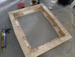
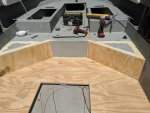
So i wanted to raise up the console to a better height for me. This is what I came up with.

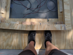
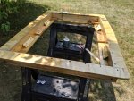
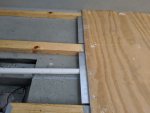
This base will raise the console about 4". I also built it with a "toe kick" all the way around for more foot room when moving around it once its mounted in the boat. I think this will really make a noticeable difference in getting from front to back along the console.

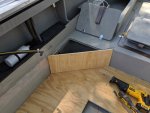
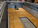
Its got a few coats of spar and some Behr deckover to match the floor.


Console Build Up1-1.pngIMG_20190803_121015.jpgIMG_20190803_143909.jpgMVIMG_20190803_150438.jpgIMG_20190807_192041.jpg
 

Attachments

  • IMG_20190803_143909.jpg
    IMG_20190803_143909.jpg
    877.4 KB · Views: 1
  • IMG_20190803_143909.jpg
    IMG_20190803_143909.jpg
    877.4 KB · Views: 1
  • IMG_20190803_1504477.png
    IMG_20190803_1504477.png
    1.6 MB · Views: 1
  • MVIMG_20190804_123845.jpg
    MVIMG_20190804_123845.jpg
    1.3 MB · Views: 0

alipinski397

Seaman
Joined
Sep 3, 2013
Messages
63
For the new top i just traced it onto a leftover piece of the 5/8 plywood, cut it out with a skill saw and jigsaw.

Sanded and beveled all the edges smooth.

It got a couple coats of epoxy and then paint to match the rest of the console.

The glued it in place. Some lead weight to hold it down while the glue dried.


IMG_20190807_164549.jpgMVIMG_20190807_165005.jpgIMG_20190807_170052.jpgIMG_20190807_181710.jpgIMG_20190810_191238.jpgIMG_20190810_191250.jpgIMG_20190813_205450.jpgIMG_20190813_205718.jpg
 

jdvasher

Petty Officer 1st Class
Joined
Jul 10, 2019
Messages
366
So anyone that followed Jason's most recent update on his thread for the 22 Islander build, you now know it found a new home with me.

Given the epic build thread and history on it I felt i needed to start a new thread continuing the legacy.

I think a little back story on how I ended up with it is in order. I had a Mariner 220V I had started a rebuild on this spring and a couple months ago had finished gutting it and got the old foam removed. That's when i found some pretty severe corrosion. Its past life was in a salt water area and i knew there could be some corrosion to fix but it was bad, really bad.

So i started searching for solutions or replacement hulls and stumbled on Jason's Islander thread. I had been considering islander hull for a replacement and cutting the top off to have the open bow center console setup of a Mariner. I realized he was local and only 25 min away, so I sent Jason a message to pick his brain on the process Not knowing if I would even get a reply as he hadn't been active on the forum for quite a while. A few days later he got back to me and low and behold he offered the islander for sale. He had back in the garage and somewhat tore back apart getting ready to convert it to an outboard. He had some other things on his plate and it had been sitting for a while collecting dust and he was ready to part with it. We made a deal and I drug it home.

My plans for the boat:
  • Finish the outboard conversion
  • Convert the dual console to center console
  • Plan to keep the bow storage and front seating structure as is
  • Add a T-top
  • Add a bow mount trolling motor
It will be a multipurpose boat for me. Duties will include fishing the great lakes, tender boat for our layout duck hunting rig in the fall and family fun boat in the summer.

Will post some photos in the replies as the thread progresses, need a few more posts in order to attach photos.

Congratulations on the new project, looking forward to watching the progress.
 

nurseman

Lieutenant Junior Grade
Joined
Jun 2, 2013
Messages
1,045
Looking good! I like the center console idea. I will tag along if you don't mind!
 

alipinski397

Seaman
Joined
Sep 3, 2013
Messages
63
After the console work I was still waiting to get the bracket back so closing back in the area of fuel fill runs was up next.

Making 45's seemed to be the best solution as rerouting the fill and vent lines seems like too much of a headache.

Glued and screwed in and I had some Durhams water putty on hand so i used that to fill in the bigger gaps.

This will all be getting a few coats of epoxy.

I will probably cut in a couple access ports later if needed.

IMG_20190811_093857.jpgIMG_20190810_143102.jpgIMG_20190811_094616.jpgIMG_20190811_100320.jpgIMG_20190816_173454.jpg
MVIMG_20190816_134333.jpg
 

Attachments

  • IMG_20190810_122647.jpg
    IMG_20190810_122647.jpg
    888.7 KB · Views: 0
  • MVIMG_20190816_134333.jpg
    MVIMG_20190816_134333.jpg
    920.6 KB · Views: 0

alipinski397

Seaman
Joined
Sep 3, 2013
Messages
63
Got the bracket back and went to work lining it up and drilling holes.

I did a lot of measuring and remeasuring to come up with the height. So hopefully I got it right.

The outboard hole pattern was already drilled in the pod when i received it so i used that as a reference to get the overall mounting height. The bracket is 28" setback so based on the rule of thumb for bracket height having the cavitation plate 1" up for every 12" back I did all the math to have to about 2.25" to 2.5" above the bottom of the hull when installed at the outboards lowest hole. Then I can use the extra holes in the outboard to go higher if needed.

That should keep the pod as low as possible to take advantage of the extra flotation it provides.

I was able to use the holes already in the transom from the stern U bolts and 2 of the IO holes. I drilled those first and secured the bracket temporarily while drilling all the other holes.

The C channel backer has some space to each side of center from the other 1/4 plate already on the transom form the IO backer. Ill use another piece of 1/4 to fill in that space when bolting it on permanently.


IMG_20190812_152610.jpgIMG_20190812_192957.jpgIMG_20190812_195836.jpgMVIMG_20190813_095204.jpgIMG_20190813_141633.jpgIMG_20190813_150440.jpgIMG_20190813_150900.jpgIMG_20190813_182111.jpgIMG_20190813_182703.jpg
 

alipinski397

Seaman
Joined
Sep 3, 2013
Messages
63
After all the holes were drilled I got going on the paint as well as installing the knee braces.


The knee braces are lag bolted into the stringers. Jason had made a nice new laminated beam so its nice and beefy. I also lag bolted it to the transom but aligned it so that a couple of the through bolts would also be holding it.

I plan on doing some kind of nonskid on the swim platform but haven't decided exactly what to use yet. First 2 thoughts are another coat of paint and the soft sand rubber material or the more expensive route - seadek? Anyone have any experience or suggestions here?


IMG_20190814_150700.jpgMVIMG_20190814_150653.jpgIMG_20190814_203110.jpgIMG_20190814_194839.jpgIMG_20190814_203057.jpgP1020222.jpg
 

alipinski397

Seaman
Joined
Sep 3, 2013
Messages
63
After the knee braces were installed and more coats of paint were going on the transom bracket I got the 3rd piece of floor down and all the screws and joints filled in.

I planned for the bilge area cut out to be small enough so the knee braces would be covered. I also had the angle gussets of the knee braces made as small as I thought possible so they would not be sticking above the floor too much and be a tripping hazard.

IMG_20190815_143648.jpgIMG_20190816_123101.jpgIMG_20190812_203911.jpg
 

Attachments

  • IMG_20190812_203917.jpg
    IMG_20190812_203917.jpg
    834.3 KB · Views: 4

alipinski397

Seaman
Joined
Sep 3, 2013
Messages
63
Next up was epoxy for the top side of the floor.

I actually got the bracket mounted in between epoxy coats (gotta take the help when its available lol) but pictures of the bracket will be the next post :friendly_wink:

You can see how the 45s step up area turned out. Should be pretty seamless once the deckover top coat is down . I also patched in a couple of the through holes from previous wiring under the old consoles.

IMG_20190816_194632.jpgIMG_20190816_202317.jpgMVIMG_20190817_175625_2.jpgIMG_20190818_082651.jpgIMG_20190818_082647.jpg
 

Attachments

  • MVIMG_20190816_202320.jpg
    MVIMG_20190816_202320.jpg
    1,001.2 KB · Views: 1

alipinski397

Seaman
Joined
Sep 3, 2013
Messages
63
And the bracket is attached. I didn't get any photos during the action as I had 5200 all over just about everything lol

I debated on repainting the transom before installing the bracket but decided just to do some touch up paint on it. That will be a project for another day in the future.

I think I got it sealed up quite well, I got pretty good squish out of the 5200 all along the inside of the bracket. Pretty happy with it.

There was one additional challenge on the outside of the transom - the original boat had an OMC keyhole, which Jason had patched the hole and converted it to a Merc keyhole. That left another gap between the bracket and transom. My best guess at measurements put it at 3/32 because 1/8 was too much couldn't find any 3/32 so I filled that with a piece of 1/16th aluminum which was all covered in 5200 as well.


MVIMG_20190817_164339.jpgMVIMG_20190817_164349.jpgIMG_20190817_164357.jpgIMG_20190819_161852.jpgIMG_20190819_122249.jpgP1010130.jpg
 

alipinski397

Seaman
Joined
Sep 3, 2013
Messages
63
After the bracket was installed it was back to work on the floor.

I filled in the large gouges in the side panels from the demo job and roughed up the epoxy with 80 grit sand paper.

Wiped it all down with acetone and rolled on a couple coats of Behr Deck over. I was't able to match the exact color but the front seating area will be covered by the cushions and that just leaves the sidewalls of the boat with the original color. A little 2 tone effect is OK with me.

IMG_20190819_194718.jpgMVIMG_20190820_114917.jpgIMG_20190820_114934.jpg
 

ben2go

Chief Petty Officer
Joined
Jul 29, 2008
Messages
411
Pretty sweet. You're really making quick work of this redux.
 

alipinski397

Seaman
Joined
Sep 3, 2013
Messages
63
Next up was figuring out how to support the bilge hatch as it will see a lot of foot traffic while fishing. My original idea was to attach supports to the sides of the stringers or make a boxed in frame all on its own inside the void. I had figured I would be able to do that without needing to use any fasteners through the top of the floor that way.

I decided against going through the side of the stringers since the wood is laminated plywood and the screws would be going through the side of the plys and I didn't want to compromise the integrity of the stringers over time.

So I ended up with some rivets through the top side of the floor along with some angle supports riveted into the knee braces.

I counter sunk the floor rivets and will just epoxy fill, sand the area a little and touch up with the deck over. I think it will be just fine.

I will also add some hinges to it as well.


IMG_20190827_132309.jpgIMG_20190827_132316.jpgIMG_20190827_132817.jpgMVIMG_20190827_132257.jpg
 

alipinski397

Seaman
Joined
Sep 3, 2013
Messages
63
Now on to the fun stuff! Things are coming together.

Base and center console getting installed. Ran the plumbing for the livewell. Extended the fuel line hoses and mounted the tank switch back in the original spot Jason had it.

When i refurbed the console I had glued some "mounting blocks" on the inside of the console to have more and better places to mount and organize wiring.

The main starting battery and house battery will also be installed under the console.

I mounted the battery switch, main fuse, terminal block and ground bus bar on the inside starboard side of the console.

The main switch panel was installed and wired to the terminal block. This will keep all the connections at an easy reach.

All the wiring connections get adhesive heat shrink connectors.

The bilges were wired up and switches for each one installed. Both have manual and Auto mode.

Controls and wiring for the outboard were also started at this point.


Click image for larger version  Name:	IMG_20190827_115524_01.jpg Views:	1 Size:	1,019.9 KB ID:	10795118Click image for larger version  Name:	IMG_20190827_143802.jpg Views:	1 Size:	1,009.7 KB ID:	10795119Click image for larger version  Name:	IMG_20190827_151333.jpg Views:	1 Size:	1.12 MB ID:	10795120Click image for larger version  Name:	IMG_20190827_155555.jpg Views:	1 Size:	806.8 KB ID:	10795121Click image for larger version  Name:	IMG_20190827_155558.jpg Views:	1 Size:	813.0 KB ID:	10795122Click image for larger version  Name:	IMG_20190827_155828.jpg Views:	1 Size:	811.3 KB ID:	10795123Click image for larger version  Name:	IMG_20190827_164139.jpg Views:	1 Size:	914.3 KB ID:	10795124Click image for larger version  Name:	IMG_20190827_164144.jpg Views:	1 Size:	949.9 KB ID:	10795125Click image for larger version  Name:	IMG_20190827_171946.jpg Views:	1 Size:	986.0 KB ID:	10795126Click image for larger version  Name:	IMG_20190827_192818.jpg Views:	1 Size:	1,005.8 KB ID:	10795127Click image for larger version  Name:	IMG_20190827_194856.jpg Views:	1 Size:	949.7 KB ID:	10795128
 

alipinski397

Seaman
Joined
Sep 3, 2013
Messages
63
Next was mounting the livewell pump. I made a Z style bracket out of left over aluminum channel and attached it to one of the ribs in the bilge area with a couple rivets. A couple of really short machine screws into the side of the aluminum stringer for extra support from tipping worked great.

The flowrite control valve and pump were mounted to the top of that bracket.

IMG_20190828_143649.jpgIMG_20190828_144031.jpgIMG_20190828_144820.jpgIMG_20190828_153306.jpg
 
Top