1974 Starcraft SS16 Restortation

FIGMO

Petty Officer 1st Class
Joined
Jun 18, 2017
Messages
320
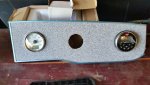
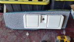
Great intro to your SS, all the damage you have is very common with these boats due to use with rot compromised transom wood and decking. I see you have the original configuration with the head knocker seats. You can make your SS into what ever you want her to be as far as layout goes

In your profile add a resto link to your signature line like I have in mine so others can find and visit your thread. As far as SS16 threads go, oh man there's a ton of them underway right now in various stages. Just take a look here in the SC section upper level.
http://forums.iboats.com/forum/owners-groups-by-manufacturer/s/starcraft-boats

Hey Watermann, it is a space issue for me in the back of the boat as I want the space for 2 x fuel tanks under the splash well. I can't place 2 x fuel tanks and 2 x batteries under the splash well. My only choice is to move them forward at this point. I am too far along to put them anywhere else. As a result I need to determine if I can get away with 4 AWG line, or do I need 2 AWG for a 20 foot length.
 

Watermann

Starmada Splash of the Year 2014
Joined
Jan 12, 2013
Messages
13,753
I see, yeah I'd use 2 AWG battery cable for 20'. Also you don't want to use welding cable, too many strands and wrong type of shielding on wire..
 

SHSU

Lieutenant Junior+Starmada Splash Of The Year 2019
Joined
Mar 8, 2017
Messages
1,665
Some reference on wire lengths a sizing:
Never mind, Iboats wont let me reference the site, so here is a picture:

Wire run.PNG
With that said, I know you said you can't have two back there, but what about just one? I run with a starter in the back and two house batteries up front. Plus I like the idea of not running my starter battery down with my livewell and other boat electronics.

SHSU
 

FIGMO

Petty Officer 1st Class
Joined
Jun 18, 2017
Messages
320
Watermann and SHSU, thanks for your input. It is always appreciated!

I went out and bought 25' of Black and Red 2 AWG battery cable. This will be more than enough to get me from front to back, and hopefully with little voltage drop off. To connect the House battery to the Starter battery via the battery Switch, I also bought 25' of Black 4 AWG. I will use that to link the batteries. It will be enough to do both the positive and negative. I will put some Red shrink wrap on the positive feed so I don't get them mixed up.

At the end of the day I learned a lesson I should have already known. If the price is too good to be true, then the odds are it is too good to be true, or I am not reading the fine print. My Admiral got a new set of booster cables for her truck so not a total loss. At the end of the day I am out 40 bucks for not paying attention. Not a lot in the grand scheme of things, and I have certainly wasted more in a stupider fashion.

I now feel better moving forward with the 2 AWG wire.

Here is a blurry useless photo of my wire boxes:

Click image for larger version  Name:	38.jpg Views:	1 Size:	146.4 KB ID:	10883648
Not very sexy and blurry (not sure why my camera is being such a pain), but it is proof.

Some wiring stuff coming up next!
 

FIGMO

Petty Officer 1st Class
Joined
Jun 18, 2017
Messages
320
Before I started wiring the boat I was looking at an 8 switch gang panel with USB, Cig Lighter, DC out and and Voltage read out. I also picked up a Blue Sea Fuse Block to run all my components through. However, I did not like the way the gang panel was set up so I re-wired it so I could incorporate the Fuse Block. I also got 2 x bus bars for components that had inline fuses. Such as the USB, Cig Lighter etc.

The fish finder, horn, compass and stereo will all be linked via the Fuse Block so I can take advantage of that particular system.

This is what I have to wire:

- nav lights (done)
- deck lights (done)
- storage lights (done)
- bilge pump (hard wired to the Starter battery with float switch, and manual control switch) (done)
- live well pump (done)
- aerator pump (done, but not connected yet as the live well will be one of the last things I put in)
- fish finder
- stereo
- compass
- horn
- trolling motor (hard wired to the House Battery with 60 amp inline fuse and 8 AWG wire)

Here are some pictures of me mutilating the gang switch so I could get it to where I wanted for my vision of the wiring:

39a.jpg

Its seems pretty convoluted at the beginning, but I watched some videos and figured out what I had to do in order to re-wire the thing the way I wanted it.

40 (2).jpg
I took the positive feeds off of the USB etc, and will run a direct line for these to the bus bar with the inline fuses.

41.jpg
Next was to take the positive feeds from the switches so that I can link them all independently to the Fuse Block.

42 (2).jpg
This is the finished stripped down version with the negative feed, and the positive negative feeds for the LED lights on the switches. These were linked directly to the Fuse Block with a 3 AMP fuse. These are the little lights that are on all the time. The main LEDs only go on with the switch is activated.

43.png


My diagram so that I could make sense of things. This actually helped me.


44.png

This is a diagram of the back of each switch on the gang panel so that I could remember what was what. It helped.

I will post some pictures of the wiring that has been competed in a few days. Maybe with some photos of the lights and what not.
 

classiccat

"Captain" + Starmada Splash Of The Year 2020
Joined
Dec 20, 2010
Messages
3,405
Watermann and SHSU, thanks for your input. It is always appreciated!

I went out and bought 25' of Black and Red 2 AWG battery cable. This will be more than enough to get me from front to back, and hopefully with little voltage drop off. To connect the House battery to the Starter battery via the battery Switch, I also bought 25' of Black 4 AWG. I will use that to link the batteries. It will be enough to do both the positive and negative. I will put some Red shrink wrap on the positive feed so I don't get them mixed up.

At the end of the day I learned a lesson I should have already known. If the price is too good to be true, then the odds are it is too good to be true, or I am not reading the fine print. My Admiral got a new set of booster cables for her truck so not a total loss. At the end of the day I am out 40 bucks for not paying attention. Not a lot in the grand scheme of things, and I have certainly wasted more in a stupider fashion.

I now feel better moving forward with the 2 AWG wire.

Some wiring stuff coming up next!

Nice job on the switch wiring FIGMO! :thumb:

Before you crack open those 2AWG boxes, did you happen to check how many amps your starter will pull?

I'm guessing well north of 100A (there are many threads on this)...referring to the chart that SHSU posted.

fetch
 

Watermann

Starmada Splash of the Year 2014
Joined
Jan 12, 2013
Messages
13,753
After reading again this morning I see that my brain had thought 2/0 when thinking of battery cables. I do know that a small 2 stroke motor starter draws a lot less amps than say a car motor starter, probably less than 100 amps but I would shorten the cables as much as possible under that 25' length. The voltage drop at 100 amp draw over 15' of cable length would be over 2% and the starter won't operate properly using 2 awg.
 

classiccat

"Captain" + Starmada Splash Of The Year 2020
Joined
Dec 20, 2010
Messages
3,405
After reading again this morning I see that my brain had thought 2/0 when thinking of battery cables. I do know that a small 2 stroke motor starter draws a lot less amps than say a car motor starter, probably less than 100 amps but I would shorten the cables as much as possible under that 25' length. The voltage drop at 100 amp draw over 15' of cable length would be over 2% and the starter won't operate properly using 2 awg.

The service manual for my 3cyl 70Hp (1975) specifies starter amp draw when cranking:
- 120A: American Bosch
- 135A: Prestolite
 

FIGMO

Petty Officer 1st Class
Joined
Jun 18, 2017
Messages
320
The service manual for my 3cyl 70Hp (1975) specifies starter amp draw when cranking:
- 120A: American Bosch
- 135A: Prestolite

I figured the diagram indicated that I should be good to go with 2 AWG. Base on my measurement, and I was generous, I am at 17' in length.

I think I am going to have to throw the dice on this one and see what happens on start up.
 

SHSU

Lieutenant Junior+Starmada Splash Of The Year 2019
Joined
Mar 8, 2017
Messages
1,665
I figured the diagram indicated that I should be good to go with 2 AWG. Base on my measurement, and I was generous, I am at 17' in length.

I think I am going to have to throw the dice on this one and see what happens on start up.

Any way to do a test outside of the boat prior to wiring? A simple test of hooking up the simulated length and testing should give you an idea.

With that said, the heat is going to be the bigger concern if pulling that many amps through the wrong sized wire. So prolonged attempts at starting would not be a good idea.

Personally still like trying to run a starting battery back by the motor, but again that is just me.

SHSU
 

knezzer

Petty Officer 1st Class
Joined
Apr 8, 2012
Messages
214
Oh wow man ! I just got caught up on your thread as I have'nt been around here for a while. Looking very very awesome !! Very well thought out plans ! I love the whole look of your bow section. The switch wiring looks good to me. As for the starter cable... I think the #2AWG copper should be fine.
 

FIGMO

Petty Officer 1st Class
Joined
Jun 18, 2017
Messages
320
Any way to do a test outside of the boat prior to wiring? A simple test of hooking up the simulated length and testing should give you an idea.

With that said, the heat is going to be the bigger concern if pulling that many amps through the wrong sized wire. So prolonged attempts at starting would not be a good idea.

Personally still like trying to run a starting battery back by the motor, but again that is just me.

SHSU

SHSU, that is a brilliant idea. In fact I plan on doing a start in about 4 days. First I have to sort out my wires. The control and motor wires are pretty rough so I am cleaning them up. I have the motor on a portable stand so I will just wheel it outside and fire it up with the wiring as it will be in the boat.

If it doesn't work, then I will think about relocating the starter battery.

Thanks for the idea.
 

FIGMO

Petty Officer 1st Class
Joined
Jun 18, 2017
Messages
320
Oh wow man ! I just got caught up on your thread as I have'nt been around here for a while. Looking very very awesome !! Very well thought out plans ! I love the whole look of your bow section. The switch wiring looks good to me. As for the starter cable... I think the #2AWG copper should be fine.

Hey knezzer, long time no see. Thanks for that. I am really hoping to be able to leave the batteries in the front of the boat. It will allow more room under the splashwell for the fuel tanks. Plus I have to consider that the dual bank charger is located in the bow. If I relocated the starter battery to the rear, then I complicate life with the charger as well.

Like SHSU recommended, I am going to do a test start with the 2AWG cut to length, and see what happens. If its a soup sandwich, then I may have to reconsider where I position the batteries (and the charger).

If I do reposition, I think my only option will be to create a box opposite of the live well on the starboard side, and relocate the battery charger to the same place. If I do that, then I end up with a lot more storage in the bow of the boat which naturally is a good thing. However, I start to clog up the back of the boat which is a bad thing (at least for me it is). That starboard space was intended to be for a cooler. Not to mention that fact that the batteries will now be on the same side as me (230 Lbs), and I think that will throw the boat out of balance with 100 Lbs of batteries added to my body weight.

Good to see you back!
 

FIGMO

Petty Officer 1st Class
Joined
Jun 18, 2017
Messages
320
I need some help with my old steering cable. I don't know how to pull off the old end to get the casing off. Mine is transom mounting steering system.

See the pictures,

Click image for larger version  Name:	45.jpg Views:	1 Size:	215.3 KB ID:	10886409

Here is the casing that is secured to the transom mount. I need to remove, but not sure how to get the end off.

Click image for larger version  Name:	46.jpg Views:	1 Size:	253.5 KB ID:	10886410

The casing is in pretty rough shape, although it was steering well with no binding.

Click image for larger version  Name:	47.jpg Views:	1 Size:	81.3 KB ID:	10886411

I know for sure it is an 11 foot cable.

Click image for larger version  Name:	48.jpg Views:	1 Size:	254.0 KB ID:	10886412

I thought the end would unscrew, but it doesn't seem to want to come off.


Click image for larger version  Name:	49.jpg Views:	1 Size:	171.1 KB ID:	10886413

The sleeve at the top pulls back and the ball joint comes out.


Click image for larger version  Name:	50.jpg Views:	1 Size:	201.2 KB ID:	10886414

Ball joint removed.


Click image for larger version  Name:	51.jpg Views:	1 Size:	224.7 KB ID:	10886415
The rotary system itself seems to be in good shape.


Click image for larger version  Name:	52.jpg Views:	1 Size:	209.1 KB ID:	10886416

If anyone knows how to remove that end piece, I would be very grateful. I am wondering if this will affect the type of steering cable I am able to use?
 

Watermann

Starmada Splash of the Year 2014
Joined
Jan 12, 2013
Messages
13,753
Your motor should have a tilt tube on it, you won't need all that transom mount stuff if you put the new cable in the tube and use a steering arm to the motor like most have.

A new steering cable won't have that hole in the very end for that piece you want to unscrew.

y4mmdWPMnmCBtWnQ_bw39OhcbFyIGjVxSp9Hx75k38rZMcDhnwd7BMnACYcA2LaUfS_VKioebFZxpVVj893pGPrW8MBunuO-c7Pivn-7MCcGVwd7Yw8Q4Rs1vcGfECwJ_LOs4nGZKBx-0xKiwppEphetzeQUkNiNlBL1sT4UmtLV82sKt_I7qUU_bHVd7eeRhiR5QX1XCTPc1e1WUwEJmG9tQ
 
Last edited:

SHSU

Lieutenant Junior+Starmada Splash Of The Year 2019
Joined
Mar 8, 2017
Messages
1,665
As Watermann said should have a tilt tube. With that said, a new cable is ~$100 and an additional ~$50 gets you the entire kit.

SHSU
 

FIGMO

Petty Officer 1st Class
Joined
Jun 18, 2017
Messages
320
Hey Gents,

So taking Watermann' s and SHSU's advice, I will look to upgrade to a through tilt tube system. Now I have four holes to plug in the transom from the old transom mounting steering, but no big deal.

In order to proceed with the tilt tube mount, I have a few questions before I start ordering stuff on line. See pictures:

Click image for larger version  Name:	53.jpg Views:	1 Size:	155.7 KB ID:	10889955

Because I am a neophyte when it comes to certain aspects of boats, I am going out on a limb in assuming the dark tube caked in grease is in fact my tilt tube? So I should be okay there. I will be cleaning that up.

Click image for larger version  Name:	54.jpg Views:	1 Size:	143.1 KB ID:	10889956

This is a used steering shaft that I picked up yesterday. I am again assuming that this should be good to go.

Click image for larger version  Name:	55.jpg Views:	1 Size:	179.7 KB ID:	10889957

Picture of the old rotary helm. There is no play in this so I am hoping to reuse it. I believe that I need to get an adapter for the quick release for the newer replacement cables? The thing with the old helm is that it is already fitted to the new dashboard. If I am required to change the helm, and it has a different mounting system, then all the work I have done on the new dashboard is junk . See Picture of new dashboards:

Click image for larger version  Name:	57.jpg Views:	1 Size:	196.5 KB ID:	10889959


The above is my math, according to the guide in the diagram. The original transom mounted steering cable was 11' long as depicted in an earlier post. According to the guide, if I go with through tilt tube steering I will require a 13' replacement cable. Does this look right to the experts in the room?

I am also curious as to whether or not I am missing something here. Are there parts I am missing that I need to get in order to upgrade my steering system as part of the rebuild???
 

Attachments

  • 57.jpg
    57.jpg
    196.5 KB · Views: 5
  • 58.jpg
    58.jpg
    142 KB · Views: 5
Last edited:

SHSU

Lieutenant Junior+Starmada Splash Of The Year 2019
Joined
Mar 8, 2017
Messages
1,665
The steering wheel mount is generally universal, so shouldn't be much off what you already have if any.

As for the length, I went with 14' but that was also because how my splashwell redesign required a little more length to get around the livewells.

What I got: Seastar SS137xx Safe-T Quick Connect Rotary Steering System in 14' length.

Only thing that didn't come in the kit was the steering arm (which looks like you got) and a steering wheel.

SHSU
 

Watermann

Starmada Splash of the Year 2014
Joined
Jan 12, 2013
Messages
13,753
The dash mounting in my experience has been if you go from one rotary helm to another no difference.

Yes clean that tilt tube out spotless as you can. I used a shotgun cleaning rod and wire brush and finish with a light coat of grease inside.

The steering arm looks right to me,.
 
Top