Crawson89
Cadet
- Joined
- May 10, 2022
- Messages
- 6
Hey! First post here, been reading for years!
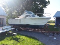
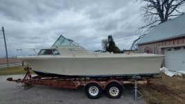
After completing a refit and refinish of my 1969 viking 22 sailboat, bulkhead replacement, sole replacement, re-coring and spraying fresh gelcoat across the entire topside, I have acquired a 1970 Stamas Clearwater 24' project. I had planned to flip for the value of the trailer, but her lines grew on me, and I've committed.
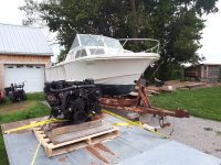
I am an experienced glass/gelcoat tech and apprentice marine mechanic. I'm comfortable with a project of this size, with dealership access to parts. Have a gm 305 5.0L v8 and alpha 1 gen 1 in good working order to drop into the boat. Originally came with a mercruiser "160" which I cannot find much info on but believe it would've been a ford inline 4 and pre alpha drive. All electrical is already designed and mostly purchased.
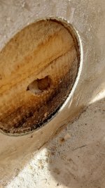
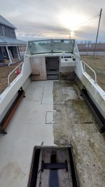
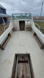
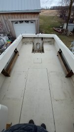
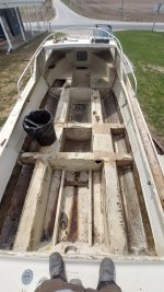
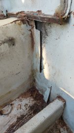
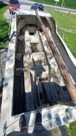
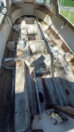
I'm currently in the demo process and have removed rotten cockpit sole and am deciding how to proceed with these stringers.. after speaking with Stamas i was expecting solid Doug fir stringers, but came up with foam filled glass stringer/bulkhead skeleton. It appears to have been laid up in a mold upside down, and filled with foam. Then flipped over and glued into the hull. The foam core does not extend all the way down to the hull. The foam coring has de-bonded from inside of stringers, how structural do we think the foam is? I was planning to tab the stringers down, as I'm not happy with original bonding putty holding it all to the hull, but wondering if i should be grinding out all the foam from 6" access holes, refilling with expanding foam and capping with glass before the new floor goes on...
Also, toying with idea of using 1/2" nidacore to replace old 3/4 ply waterlogged floor? Thoughts?
Open to all constructive guidance, opinions, thoughts etc!
Thanks!
After completing a refit and refinish of my 1969 viking 22 sailboat, bulkhead replacement, sole replacement, re-coring and spraying fresh gelcoat across the entire topside, I have acquired a 1970 Stamas Clearwater 24' project. I had planned to flip for the value of the trailer, but her lines grew on me, and I've committed.
I am an experienced glass/gelcoat tech and apprentice marine mechanic. I'm comfortable with a project of this size, with dealership access to parts. Have a gm 305 5.0L v8 and alpha 1 gen 1 in good working order to drop into the boat. Originally came with a mercruiser "160" which I cannot find much info on but believe it would've been a ford inline 4 and pre alpha drive. All electrical is already designed and mostly purchased.
I'm currently in the demo process and have removed rotten cockpit sole and am deciding how to proceed with these stringers.. after speaking with Stamas i was expecting solid Doug fir stringers, but came up with foam filled glass stringer/bulkhead skeleton. It appears to have been laid up in a mold upside down, and filled with foam. Then flipped over and glued into the hull. The foam core does not extend all the way down to the hull. The foam coring has de-bonded from inside of stringers, how structural do we think the foam is? I was planning to tab the stringers down, as I'm not happy with original bonding putty holding it all to the hull, but wondering if i should be grinding out all the foam from 6" access holes, refilling with expanding foam and capping with glass before the new floor goes on...
Also, toying with idea of using 1/2" nidacore to replace old 3/4 ply waterlogged floor? Thoughts?
Open to all constructive guidance, opinions, thoughts etc!
Thanks!
Attachments
-
 20210815_091625.jpg6.7 MB · Views: 23
 -
 20210904_175207.jpg6.3 MB · Views: 24
 -
 20220301_180609.jpg4.6 MB · Views: 22
 -
 20220412_192208.jpg1.5 MB · Views: 18
 -
 20220416_121405.jpg1.3 MB · Views: 17
 -
 20220416_121352.jpg1.4 MB · Views: 19
 -
 20220430_151858.jpg1.8 MB · Views: 21
 -
 20220416_121235.jpg2.4 MB · Views: 19
 -
 20220421_183201.jpg3.8 MB · Views: 17
 -
 20220421_183357.jpg2.4 MB · Views: 22


")