1963 Mercury 650 restoration

MPrimeaux

Petty Officer 1st Class
Joined
May 10, 2019
Messages
240
Well----.5 Ohms is NOT open.-----Open would show infinity !!

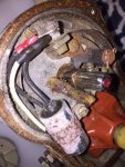
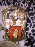
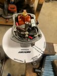
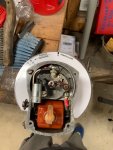
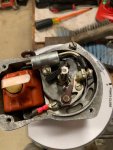
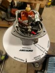
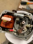
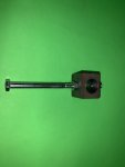
I realize that. Seems like I read somewhere in this venture that an analog meter was needed to set points because a digital VOM wasn't sensitive enough. The manual says advance the mag until the points "break". I can see the needle clearly move at approximately where the spark advance stop was before I moved it. Actually, the needle makes the same movement 4 times per revolution of the flywheel. That is what I expected being a 4 cylinder and having 4.... lobes??? on the shaft of the magneto. I'm an electrician by trade and I realize what an open is, that's the reason for my question. Is the .5 ohms the "break" that I'm looking for or should I get a true open and I've got something wrong. If I have something wrong, does anyone have an idea what that may be? As I said in a previous comment (and I took pictures of my test), I'm having trouble wrapping my head around how I would ever get an open with the magneto housing grounded. I've been looking at the pictures of the magneto before I replaced points and bearings and the only thing I can guess is I've got something touching either the terminal on the points, the main magneto ground terminal, or the points simply aren't opening. I used a dwell plate and pointer to set the 48 degrees, but maybe I didn't tighten the screw or something?
 

racerone

Supreme Mariner
Joined
Dec 28, 2013
Messages
36,480
????-------I would say the .5 ohm reading is the points CLOSED.------1,000,000 ohms would be OPEN
 

MPrimeaux

Petty Officer 1st Class
Joined
May 10, 2019
Messages
240
????-------I would say the .5 ohm reading is the points CLOSED.------1,000,000 ohms would be OPEN

Ok, thanks racer. I've never messed with points and wasn't sure if that little jump was what I was looking for or not. I'll open up the mag again and see if I've got something shorted in there or if I forgot to tighten down the set screw on the points and they've moved or something.
 

MPrimeaux

Petty Officer 1st Class
Joined
May 10, 2019
Messages
240
I also looked back and realized that I don't think I posted any pictures of my magneto internals after I rebuilt it. Here are some before and after pictures.
 

Attachments

  • photo313512.jpg
    photo313512.jpg
    155.2 KB · Views: 2
  • photo313513.jpg
    photo313513.jpg
    150.6 KB · Views: 2
  • photo321277.jpg
    photo321277.jpg
    82.7 KB · Views: 2
  • photo321278.jpg
    photo321278.jpg
    86.5 KB · Views: 2
  • photo321279.jpg
    photo321279.jpg
    88.2 KB · Views: 2
  • photo321280.jpg
    photo321280.jpg
    81.2 KB · Views: 2
  • photo321281.jpg
    photo321281.jpg
    86.7 KB · Views: 2
Last edited:

MPrimeaux

Petty Officer 1st Class
Joined
May 10, 2019
Messages
240
Just in case someone might could use this. I found an image of a PDF of a dwell plate and instructions for making a pointer for a mercury 4 cyl. somewhere online. Can't remember where, but I was able to blow it up a little and print it out. I cut the dwell plate out and then laminated it to make it rigid enough. I then cut out the hole in the center with a razor knife until it fit snugly on the magneto (loose enough to get it over the lip, but tight enough to stay in place when set in place). Built the pointer out of some 1" steel square stock, a 1/4 X 3" bolt, and I believe a #8 X 3/4" scew. I really needed a 4" bolt, but 3" did work... barely.
Click image for larger version  Name:	8428_DwellPlate4Cyl.jpg Views:	1 Size:	64.6 KB ID:	10804274Click image for larger version  Name:	IMG_2015.jpg Views:	1 Size:	59.4 KB ID:	10804272Click image for larger version  Name:	IMG_2016.jpg Views:	1 Size:	64.8 KB ID:	10804273
Click image for larger version  Name:	IMG_2012.jpg Views:	1 Size:	47.1 KB ID:	10804275
 

Attachments

  • IMG_2012.jpg
    IMG_2012.jpg
    47.1 KB · Views: 0
  • IMG_2013.jpg
    IMG_2013.jpg
    44.8 KB · Views: 0
  • IMG_2014.jpg
    IMG_2014.jpg
    61.7 KB · Views: 0

MPrimeaux

Petty Officer 1st Class
Joined
May 10, 2019
Messages
240
Also in case someone is curious and might could use this, I looked for the mercury timing tools and didn't find any that wouldn't require a loan to purchase. So, I built one. Took an old spark plug and broke the insulator and electrode out of the center (that's a lot more difficult that it sounds, but it can be done... broke one punch, bent another), then welded a washer and a nut on the outside that would fit a long fully threaded bolt. ( I also filed the tip of the bolt flat and smooth as to not scratch the piston) Added another nut to lock the bolt down when in place. Screwed the assembly into #1 cylinder and screwed bolt in until I found TDC, snugged the lock nut, used a set of dial calipers to measure between lock nut and bolt head, subtracted the .222", adjusted the screw to that measurement and then re-snugged the lock nut. Turned the flywheel around again till it stopped on the end of the bolt. Boom. :tea: Probably a lot more than necessary, but I was attempting to do it by the book. Anyways.... some pics. IMG_2002.jpg
 

Attachments

  • IMG_2002.jpg
    IMG_2002.jpg
    86.9 KB · Views: 0
  • IMG_2009.jpg
    IMG_2009.jpg
    59.9 KB · Views: 0
  • IMG_2008.jpg
    IMG_2008.jpg
    63.4 KB · Views: 0
  • IMG_2010.jpg
    IMG_2010.jpg
    56.6 KB · Views: 0

MPrimeaux

Petty Officer 1st Class
Joined
May 10, 2019
Messages
240
ok, I've taken the magneto back apart and found what I'm reading. I'm reading the coil. One wire of the coil is attached to the frame of the magneto, the other is attached to the terminal on the points, so when the points open I'm reading through the coil to the frame (ground). Disconnected both wires on the coil and measured that resistance... yep.. about .5 Ohms. So that little "break" I'm seeing with the magneto installed IS the points opening, my problem is I'm not sure if that's what I should be seeing or if I have an issue with the coil. The coil test data sheet from the manual says the secondary should be between 55 - 65. I'm not sure what unit of measurement they are referring to. The primary column on the same chart specifically states "Ohms", but not the primary. I get about 9k Ohms from the copper output arm to either wire of the coil, although I'm not exactly sure what I'm measuring there. Can anyone give me a solid go/no go on this from experience? To me it looks like I might have a shorted coil, but I'm not 100% on what measurements I should be getting and where I should be taking measurements. Thanks for being patient with me, I hate being so needy! IMG_2017.jpgIMG_2018.jpg
 

GA_Boater

Honorary Moderator Emeritus
Joined
May 24, 2011
Messages
49,038
Of course continuity is OHMS, it can't be anything else. For primary check, measure across the coil, the two disconnected circled lugs. Not to ground or the points or anything else - Across the coil.

Secondary is with the wires connected and measure from ground to the the spring strap on top of the coil.

Look, put the magneto back together, lick a finger and put it on the kill stud. Then spin the shaft. You'll know if the magneto is working. It's really that simple.

Set the points, button up with the cap and rotor and start figuring out the timing screw setting.
 

MPrimeaux

Petty Officer 1st Class
Joined
May 10, 2019
Messages
240
Of course continuity is OHMS, it can't be anything else. For primary check, measure across the coil, the two disconnected circled lugs. Not to ground or the points or anything else - Across the coil.

Secondary is with the wires connected and measure from ground to the the spring strap on top of the coil.

Look, put the magneto back together, lick a finger and put it on the kill stud. Then spin the shaft. You'll know if the magneto is working. It's really that simple.

Set the points, button up with the cap and rotor and start figuring out the timing screw setting.

Ok. Thanks. It's given me a tingle a couple of times, so I know it's doing something. GA.... I realize that ya'll are probably thinking that I am a complete moron. I will probably look back on this one day and see the same thing. (After reading the continuity being Ohms statement, I kinda want to slap myself a couple of times) I think I'm still hung up on this mercotronic thing. I keep trying to make this instrument that I've never seen some sort of magic box with coded readings I guess. Thanks again for being patient with me.
 

MPrimeaux

Petty Officer 1st Class
Joined
May 10, 2019
Messages
240
Well, got it all back together and timing set. Can't tell you how good it felt to hear it run. Ran great... Fired right up after I got fuel to the carbs. Shifted into forward and reverse without issue. It doesn't quite return to the idle stop, I suspect maybe the spring is weak, but it still runs great and I'll put it in the water to see before I change anything. If you care to see and hear you can find the video here.

https://www.youtube.com/watch?v=DYQKFj_tvpA

Thanks again to everyone that was patient enough to give me advice. Next on my agenda is to put my 1957 Fleetform Custom in the water with this engine to see how it floats to determine if the fuel tank needs to go under the bow or can stay in the aft. Then I will be replacing stringers and transom and also tearing this motor back down for paint and decals. I'll keep you posted!!
 

MPrimeaux

Petty Officer 1st Class
Joined
May 10, 2019
Messages
240
Had a small victory today. Scored a SS Quicksilver 19P prop for $40 on marketplace! May be too steep of a pitch, but for $40 it'll be a good spare anyways.
 

Attachments

  • photo321428.jpg
    photo321428.jpg
    168.5 KB · Views: 0
  • photo321429.jpg
    photo321429.jpg
    149.7 KB · Views: 0

MPrimeaux

Petty Officer 1st Class
Joined
May 10, 2019
Messages
240
I ran into something the other day that I was hoping to get some input on. When I changed out my prop, I noticed after tightening it down, it wouldn't turn. Had to back off on the nut a little (not to the point of having slack, but a little) to get the prop to spin freely. Doesn't seem right to me. Does anyone know off the top of their head or better yet have some pictures of the thrust hub/washer assembly from a 1963 Mercury 650 for me to compare what I have to?? I'm pretty sure that the part numbers that I have don't match up to what I should have, but from what I understand this motor was used with these parts before it sat up. My serial # is 1543001 for reference and I've included pics of what I have. Thanks for any help!!
 

Attachments

  • photo321842.jpg
    photo321842.jpg
    166.1 KB · Views: 0
  • photo321843.jpg
    photo321843.jpg
    132.4 KB · Views: 0
  • photo321844.jpg
    photo321844.jpg
    78.4 KB · Views: 0
  • photo321845.jpg
    photo321845.jpg
    166.2 KB · Views: 0
  • photo321846.jpg
    photo321846.jpg
    169.5 KB · Views: 0
  • photo321847.jpg
    photo321847.jpg
    88.4 KB · Views: 0
  • photo321848.jpg
    photo321848.jpg
    124.2 KB · Views: 0

Big Jay

Petty Officer 1st Class
Joined
Aug 7, 2012
Messages
244
Hey man, I just wanted to acknowledge this thread.. for someone with little to no outboard experience, you did great. And that's a fine looking rig, can't wait to see it finished up...

Cheers..
 

MPrimeaux

Petty Officer 1st Class
Joined
May 10, 2019
Messages
240
Hey man, I just wanted to acknowledge this thread.. for someone with little to no outboard experience, you did great. And that's a fine looking rig, can't wait to see it finished up...

Cheers..

Thanks man. I've been at work for a while and haven't had a chance to do much on it since the last post. I go home tomorrow and the plan is to re-wire the controls, change the steering cable, build a bracket to attach the steering cable to the motor, put the helm back in the boat and just go put it in the water to see how it sits in the water. The rest of the project revolves around where I'm going to put the gas tank. After I decide that..... I guess it'll be time to break out the grinder! I'll keep everyone posted.
 

MPrimeaux

Petty Officer 1st Class
Joined
May 10, 2019
Messages
240
Had a couple of days to work on the boat this week. Got the help put back in, steering bracket fabricated (still have to clean it up some and paint), tiller cable replaced, remote controls torn apart and cleaned (that was NOT fun, thank God for manuals), and the remote side of the wiring harness repaired. I did some continuity checks on the switch and it seems flaky to me. May have to replace that. I do have a couple of questions for the more experienced peeps.....

1. The wiring diagram for this engine (can be seen on page one of this thread) shows that after a certain year, a wire was ran connecting the rectifier directly to the + battery (red) cable in the harness, mine does NOT have that wire. Anyone see a reason why I can't just run a wire from the rectifier to the the red cable on the starter solenoid to prevent damage to the rectifier if the engine were to die at speed? Electrically it would be the same thing the way I see it, but I've missed obvious things before.

2. I did some continuity checks on the ignition switch and it seems a little flaky according to my meter. Like when in the run position, if you bump the switch housing, it goes from around 25ish ohms to 200 kOhms. Seems like that's going to give me trouble and I may end up replacing the switch. My question is, replacement parts... It has a Mercury 30162 ignition switch that was replaced by a Mercury 54211T, which is like $70. I found another switch for mercury magneto outboard with the push to choke key that I think will work. Anyone know for sure?
View attachment swich capture.pdf

3. Also, not sure if this is the place to ask this, but.... after replacing the tiller cable, the steering seems pretty stiff. Not like two hands to turn stiff, but almost. Is that normal? The helm was frozen up when I got the boat and have never felt cable and drum steering.

Didn't happen without pictures I guess....

IMG_2310.jpg
IMG_2303.jpgIMG_2304.jpg
IMG_2313.jpgIMG_2305.jpg
IMG_2315.jpgIMG_2314.jpg
 

Attachments

  • IMG_2308.jpg
    IMG_2308.jpg
    129.5 KB · Views: 1
  • IMG_2309.jpg
    IMG_2309.jpg
    113.4 KB · Views: 1
  • IMG_2311.jpg
    IMG_2311.jpg
    134.5 KB · Views: 1
  • IMG_2316.jpg
    IMG_2316.jpg
    141.9 KB · Views: 1

GA_Boater

Honorary Moderator Emeritus
Joined
May 24, 2011
Messages
49,038
On the steering - My rebuilt drum and cable steering is easy turning one finger from lock to lock. It didn't start out that way before rebuilding it.

1st thing I would do is take off the motor tiller arm and make sure the motor swivels easily. The grease gets kinda hard and can bind the swivel. Put some new grease through the zerk(s), even if the motor turns from side to side - It can't hurt.

2nd thing is lube the pulleys and helm. After all these years, crud builds up and can bind/drag. These pulleys are nylon and the helm has nylon bushings. Powdered graphite is the stuff to use. Oil or grease can deteriorate the nylon - Graphite is safe.

Since the red cable on the solenoid is directly from the battery, the rectifier can safely be connected to the solenoid. Electrically it's matching the note;

63650wire.png
 

MPrimeaux

Petty Officer 1st Class
Joined
May 10, 2019
Messages
240
Hey GA. Thanks for the input. I appreciate any help I can get..... and I need a bunch!!
1st thing I would do is take off the motor tiller arm and make sure the motor swivels easily. The grease gets kinda hard and can bind the swivel. Put some new grease through the zerk(s), even if the motor turns from side to side - It can't hurt.

This was completed when I got the motor running. It took some cleaning and pumping a lot of grease through, but the motor swivels VERY easily. No resistance there.

2nd thing is lube the pulleys and helm. After all these years, crud builds up and can bind/drag. These pulleys are nylon and the helm has nylon bushings. Powdered graphite is the stuff to use. Oil or grease can deteriorate the nylon - Graphite is safe.

I did also remove the helm and lube it up. It was almost completely frozen when I got it. I had to completely disassemble it (including removing the nylon bushings) and polish the shaft. There is no drain hole in the bottom of the bezel and about 3/4 - 1" of water just sat in it for who knows how many years. BUT... after doing all that, the helm alone is also slick as glass.


Since the red cable on the solenoid is directly from the battery, the rectifier can safely be connected to the solenoid. Electrically it's matching the note;

That's exactly what I thought too, I just wanted to run it by someone else to make sure I wasn't missing something!


So.... couple of things to note on the steering. First, I did use marine grease on the helm. I didn't know about grease and nylon and didn't think about graphite. I'll correct that when I take everything back apart for glass/gel/paint. Second, I didn't replace the 4 pulleys in the hull, but I DID inspect them pretty good. The had no cracks or chips, were not brittle, and turned freely. I may try to put a little graphite on those... I don't suspect it will make that much difference, but it's worth a try. Third, I built my steering bracket as the motor didn't have one when I bought it. All I had was a picture to go by, but it's close. The only thing that I can think is maybe the angle of the cables where they attach to the steering bracket and the hull. With the motor in the running position, the pulley attachment point is slightly higher than where they attach to the hull. If I would have built the bracket a little longer this could have been avoided, but again... I can't see that making the difference. If one side takes up exactly the same amount that the other lets out, I shouldn't be pulling "down" on the steering bracket. I also can't see where having that cable at a specific angle should matter. If the motor had power trim, that angle would change with the trim. :smile-new: Lol.... after thinking that out to write this... the only thing that makes sense is the pulleys. I bet one of them has a bad spot in the axle hole and isn't turning now that it has tension on it. I didn't get under there to check that after I hooked everything up. I bet the cable is just sliding through one of the pulleys. I'll check that today and let you know!! Thanks again for the help brother.
 

MPrimeaux

Petty Officer 1st Class
Joined
May 10, 2019
Messages
240
Oh yeah.... and yet another set back! As I was connecting the throttle and shift cables I realized that I don't have the parts required to connect the brass drum to the arms on the motor!! :frusty: After FINALLY figuring out what these parts were called and what I needed, I found out they are also NLA. I did find them on the interweb though and they are on the way. Another $100 down in the drink!!
 

MPrimeaux

Petty Officer 1st Class
Joined
May 10, 2019
Messages
240
Small update. I lubed the pulleys up this morning and the steering is MUCH better. I didn't find a frozen pulley like I expected, but lubing the pulleys helped a bunch. The rest I'll chalk up to new, stiff cable. Waiting on clevises now to connect throttle and shift cables and hopefully off to the lake for a draft test to determine gas tank location.
 

The Force power

Commander
Joined
Feb 3, 2019
Messages
2,260
I have been following your progress from the start and I'm impressed with the outcome; love it.

I had a 1962 Arkansas traveler with pulley/cable steering so I have one tiny advice to add, that could be significant.
Check the screws/wood that the pulleys are secured into the boat with; they can come loose (not good at high speed as you loose control of any steering, luckily mine happen when docking)
 
Top