EDIT - I was writing this as you replied above. But I wrote too much to just delete it.

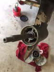
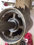
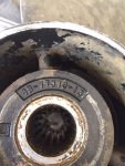
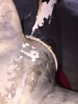
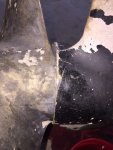
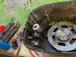
If you take the flange off the timing pulley on the magneto drive, the belt lifts off. Then you have all the slack needed to remove the flywheel. You were replacing the belt, so no harm. But for future reference, no need to cut the belt.
While the belt is off, check the magneto bearings by spinning the pulley. You will feel the magnetic flux as a rotor lobe passes the magnet, but you can also feel bearing notchiness. I had a belt break from bad bearings.
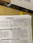
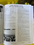
On the stator OHMs reading - OHMS is OHMs. The Mercotronic thing-a-ma-bobber setting to the left of the chart describes zeroing the meter on Scale No. 2 by shorting the leads and adjusting the needle to zero. This is a required practice when using an analog meter. A Merc-O-Tronic Magneto Analyzer was just a fancy tool for mechanics to use with a minimum of electronic training - An electronic go - no go tester.
.35 - .45 OHMS is almost a short. Use the lowest resistance scale on the meter. Try another meter unless you have a Merc-O-Tronic Magneto Analyzer sitting on the shelf.
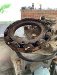
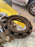
What you're measuring is the resistance of a 50 or 60 foot length of wire. It isn't much. If it isn't showing an open, the wire is good. One more thing to check is that the wire isn't shorted to the stator frame. Check the resistance between either lead and a bare spot on the frame for an open.
The last thing that could be bad with the stator is wire coils can be shorted in the wire wraps. Unless you have a Merc-O-Tronic Magneto Analyzer sitting on the shelf, about the only way to check that is with a running motor and measure the stator output AC voltage and rectifier output DC voltage. I'm not sure what the AC voltage should be, 30 - 40 VAC and increases as the RPM are raised, I think. The rectifier should be about 13 VDC above idle and increasing as the motor is revved to about 15 or 16 VDC. Your manual should have another chart with the correct voltages using a Merc-O-Tronic Magneto Analyzer.
[IMG2=JSON]{"data-align":"none","data-size":"full","src":"https:\/\/forums.iboats.com\/filedata\/fetch?photoid=10803171"**[/IMG2]