Kern Fischer
Seaman
- Joined
- Jun 24, 2013
- Messages
- 51
Because the helm station is quite constricted on the right side, the motor control was never mounted there. Instead, it was mounted on the starboard side of the center console near the front. The original control cable routing had them lying on the floor angling toward the starboard rear corner. This routing was not usually a problem because passengers were not often carried back there and when the tonneau covers were in place, the cables were not visible.
A more finished look for the rear compartment was desired so the decision was made to route the cables under the floor using a recessed channel. A tube could not be used because the size of the cable ends would not easily push through a tube, so an open channel was designed, using a gasketed cover to close the channel.
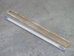
The channel was made by using a length of pvc tubing with 45 degree elbows bonded to the ends. The elbows were the same ID size as the tubing to provide more uniform sizing at the ends. The outer tube ends and the inner elbows were ground at an angle to provide more area for bonding the parts and they were attached using epoxy resin.
 One elbow bonded to the tube.
 The elbow/tube assembly.
After bonding the parts, the assembly was attached to a 2X4 board and run through the table saw to open the top of the tube assembly and create a channel. Then a surround was cut from ? inch plywood and bonded to the channel so the surface of the plywood was flush with the open top of the channel.
 Cutting the tube and elbows to create a channel.
 The channel with the wood flange that will be bonded to it.
The location of the channel was established for its under floor positioning. The foam filler and small portions of the starboard stringers were cut away so the top of the channel assembly would be at the same level as the tops of the stringers and foam. The channel was then bonded into place using resin.

The channel/flange assembly lying beside the cavity that was cut into the foam and stringers.
 The channel/flange assembly bonded into place.
Cutting into the tops of the stringers weakened them slightly in those areas. Once the channel was bonded into place some or all of that strength was restored. Bonding of the floor into place further stiffened the entire structure. When the channel cover is screwed into place, this will add more stiffness to that area. Summary - it is felt that the structural strength of the bottom was not compromised by the addition of the cable channel assembly.
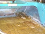
After installation of the cable channel, the floor panels could be installed. The floor was comprised of seven panels for easier fitting and installation. To install each panel, the tops of the foam and stringers in that area were fully wetted with a resin/microballoon mixture and the bottom of the floor panel was wetted with plain resin. The side edges were left dry until the main area had cured. They were then filled with a resin/microballoon mixture. The resin/microballoon mixture was selected as it could be slightly more viscous and better filled any small gaps or cavities. After complete wetting the floor panel was laid into place and weighted during resin cure. No screws were used to attach the floor panels to the stringers, so there is no place for water entry into the wood.
 The start of floor panel installation.
The floor panels were cut so the floor overlapped the edges of the cable channel surround by about ? inch all around. This overlap allowed a good resin bond and seal all around the perimeter of the cable channel to prevent water entry into the bottom structure.
 A closer view showing the overlap of the floor panels to the channel flange.
A more finished look for the rear compartment was desired so the decision was made to route the cables under the floor using a recessed channel. A tube could not be used because the size of the cable ends would not easily push through a tube, so an open channel was designed, using a gasketed cover to close the channel.
The channel was made by using a length of pvc tubing with 45 degree elbows bonded to the ends. The elbows were the same ID size as the tubing to provide more uniform sizing at the ends. The outer tube ends and the inner elbows were ground at an angle to provide more area for bonding the parts and they were attached using epoxy resin.
One elbow bonded to the tube. The elbow/tube assembly.After bonding the parts, the assembly was attached to a 2X4 board and run through the table saw to open the top of the tube assembly and create a channel. Then a surround was cut from ? inch plywood and bonded to the channel so the surface of the plywood was flush with the open top of the channel.
Cutting the tube and elbows to create a channel. The channel with the wood flange that will be bonded to it.The location of the channel was established for its under floor positioning. The foam filler and small portions of the starboard stringers were cut away so the top of the channel assembly would be at the same level as the tops of the stringers and foam. The channel was then bonded into place using resin.
The channel/flange assembly lying beside the cavity that was cut into the foam and stringers.
The channel/flange assembly bonded into place.Cutting into the tops of the stringers weakened them slightly in those areas. Once the channel was bonded into place some or all of that strength was restored. Bonding of the floor into place further stiffened the entire structure. When the channel cover is screwed into place, this will add more stiffness to that area. Summary - it is felt that the structural strength of the bottom was not compromised by the addition of the cable channel assembly.
After installation of the cable channel, the floor panels could be installed. The floor was comprised of seven panels for easier fitting and installation. To install each panel, the tops of the foam and stringers in that area were fully wetted with a resin/microballoon mixture and the bottom of the floor panel was wetted with plain resin. The side edges were left dry until the main area had cured. They were then filled with a resin/microballoon mixture. The resin/microballoon mixture was selected as it could be slightly more viscous and better filled any small gaps or cavities. After complete wetting the floor panel was laid into place and weighted during resin cure. No screws were used to attach the floor panels to the stringers, so there is no place for water entry into the wood.
The start of floor panel installation.The floor panels were cut so the floor overlapped the edges of the cable channel surround by about ? inch all around. This overlap allowed a good resin bond and seal all around the perimeter of the cable channel to prevent water entry into the bottom structure.
A closer view showing the overlap of the floor panels to the channel flange.