Dillon Laker 14/16.5 Wooden Tunnel Hull Build/Mod Project

gomopar440

Petty Officer 1st Class
Joined
Nov 27, 2007
Messages
281
I remember seeing that one in your resto thread and thought it was pretty neat. I've also seen the tiger shark mouth graphic done on a lot of other types of vehicles as well, with varying degrees of success. If I decide to use it on mine, I'll want to keep it as close to the original as possible. The warbird theme seems fitting as these tunnel hulls sort of fly on the cushion of air trapped under the tunnel.

This is the one I was using as a reference pic for the rendering I did.
https://upload.wikimedia.org/wikiped...40_Warhawk.jpg
 

archbuilder

Vice Admiral
Joined
Sep 12, 2009
Messages
5,697
Cool concept Gomopar. I like it but I do twinge when motors aren't factory colors.....I just like them that way. That being said, your concept is one of the nicer ones I have seen with the factory motor painted.
 

gomopar440

Petty Officer 1st Class
Joined
Nov 27, 2007
Messages
281
Pat:
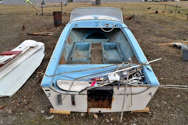
I hadn't come across that pic before. I wonder if that was Photoshopped or just staged for the pic? I can't see how that little tub could even float, let alone get underway with that monster hanging off the back.

Arch:
I generally agree with you as far as non factory paint jobs on OB's. That said, this particular paint job definitely needs the motor to be painted as well to make it all work together IMHO. If I do go with this paint scheme, I'm pretty much locked into keeping this motor with the boat. I don't have a problem with that, but I still have to think of the possible mechanical issues that could pop up with running a 32 year old OB, no matter how well taken care of it appears to have been. There's also the fact that my OD green painted TOP would look WAAAY out of place on any other boat if I ever wanted to hang it on another hull. I suppose it's nothing a little more paint couldn't cure if it ever came to that.

Now for today's progress report. The cap(s) for the DVA showed up in the mail today so I spent a few minutes soldering it in. I know I've been telling you guys about this DVA for a while now, but without pics "it didn't happen". Right? So here's the proof.
DSC_4501.jpg


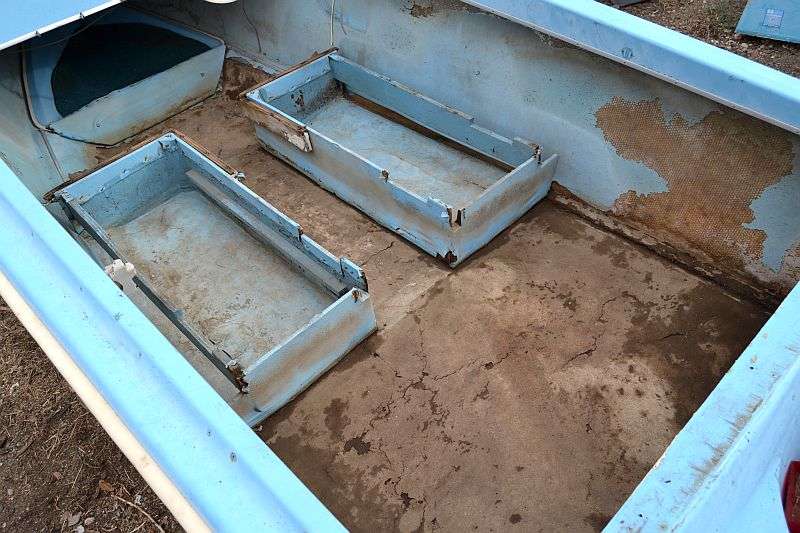
I still need to test it out yet, but I wanted to get a little more done with the sponson sides first. I propped up the port side piece and drilled some starter holes in the center of the beam locations. I then used the jig saw to cut the holes out to size. It's fine for them to be a little oversized since the beams get attached to the bulkheads to get their alignment and support. After the first side was done, I flipped it over again then aligned and reattached the two scarfed pieces together again. I used the holes to guide the jig saw to copy the holes to the opposite side.
DSC_4502.jpg


After all the beam cut outs were done, I transferred all the bulkhead station and reference lines onto the rough outboard sides. The rough sides of the ply will be facing the inside of the sponsons where the bulkheads will be attached, so that's where I need to be able to see them. I ran my hands over the outside edges while the pieces were still stuck together and faired any imperfections out with the belt sander. The inboard most deck stringer and the sponson keel will help define the actual shape on those edges.
DSC_4503.jpg


I won't have the money to get the wood for the rest of the beams until next payday (1 Nov), so those will just have to wait. What I'll do in the meantime is just go ahead and attach the bulkheads to the sponson inner sides first, without the beams. The sides will be a bit floppy without the beams to connect them, but all I really need to have is a good flat surface to work on. That way I can get the bulkheads perpendicular to the sides, and also lined up with the station and reference lines. Before I can install the sponson tip on the starboard side, I'll need to make another butt block and extension like I did for the port side and cut it to shape. I'll be using glue to permanently attach the extension and the butt blocks. The screws holding it together will only stay in place long enough for the epoxy to dry. They'll all be removed and the holes will be filled with epoxy afterwards.
 
Last edited:

gm280

Supreme Mariner
Joined
Jun 26, 2011
Messages
14,593
I like it gomopar440. I am learning from watching your build. Nice!

As for the DVA circuit. It is merely a little circuit to allows the extremely fast voltage peaks to be rectified (via the diode) to allow the capacitor to build up to the peak voltage max so you can read the voltage with your DVM (Digital Volt Meter). The resister is there to bleed off the high voltage that is on the capacitor when it is not used anymore so you don't get a nasty zap. Looks like you made a nice little box for that circuit as well. Bravo sir Bravo.
 

gomopar440

Petty Officer 1st Class
Joined
Nov 27, 2007
Messages
281
I was an Aviation Electronics Technician (AT) for my first four years in the Navy, but have forgotten a lot of it by now from lack of using that knowledge. It's been a while since I played with a lot of really in depth electrical stuff, but we used to have access to high end tools that would do this kind of stuff internally. I still like making little things like this when I can, mostly because I just like building stuff in general.

FWIW, I've needed an O-scope a few times on different projects but never could afford the ones I was able to find. Not too long ago I came across a solid state type adapter that plugs into your laptop to creates a virtual O-scope. They also have a couple optional modules that piggy back onto it to add signal generator and logic analyzer capabilities. You can get a 20Mhz or 40Mhz version, with the faster bandwidth one costing about twice as much as the slower one ($50 vs $100). If I were to pick up one of these O-scopes it would make the DVA redundant. My laptop is trying to commit suicide (blue screen of death) so I'll stick with the DVA for now. Here's a link to the O-scope adapter if you're interested. http://www.ebay.com/itm/SainSmart-DD...8AAOxyrrpTiT0l

Ok, back on topic now. BTW, is it still considered hi-jacking if I do it to my own thread? :confused:
I'm heading out to the tent now to try to warm it up enough for me to glue the bulkheads to the sponson sides.
 
Last edited:

gm280

Supreme Mariner
Joined
Jun 26, 2011
Messages
14,593
I was an Aviation Electronics Technician (AT) for my first four years in the Navy, but have forgotten a lot of it by now from lack of using that knowledge. It's been a while since I played with a lot of really in depth electrical stuff, but we used to have access to high end tools that would do this kind of stuff internally. I still like making little things like this when I can, mostly because I just like building stuff in general.

FWIW, I've needed an O-scope a few times on different projects but never could afford the ones I was able to find. Not too long ago I came across a solid state type adapter that plugs into your laptop to creates a O-scope. They also have a couple optional modules that piggy back onto it to add signal generator and logic analyzer capabilities. You can get a 20Mhz or 40Mhz version, with the faster bandwidth one costing about twice as much as the slower one ($50 vs $100). If I were to pick up one of these O-scopes it would make the DVA redundant. My laptop is trying to commit suicide (blue screen of death) so I'll stick with the DVA for now. Here's a link to the O-scope adapter if you're interested. http://www.ebay.com/itm/SainSmart-D...842593?hash=item4614277ba1:g:wa8AAOxyrrpTiT0l

Ok, back on topic now. BTW, is it still considered hi-jacking if I do it to my own thread? :confused:
I'm heading out to the tent now to try to warm it up enough for me to glue the bulkheads to the sponson sides.

First subject, I was always interested in solid state O'scopes, but since a bought a Tektronix 454 scope, I haven't been looking at them as much. But I most certainly appreciate the link all the same. You never know when I will have that urge hit me again. I am a retired Electronics Engineering Technician of 38 years. And between black box repairs (when I first started work) for all types of aircraft to computer programming and even reverse engineering and even circuit design, I keep myself in tune with electronics in general. But as you know, electronics covers so much territory these days, you simply can't keep in touch with everything out there anymore. So you pick a few electronics fields and forgo the rest to stay sane. I actually swapped a few emails with the Tektronix engineer that designed the 454 scope. He was amazing to communicate with.

Second subject, NO anything you talk about on your own thread is not hijacking. Now others going off subject could be, kind of like I am doing now. :facepalm:

Thirdly, keep the tent warm and pictures flowing. We love to see what you are doing. :thumb:
 

sphelps

Supreme Mariner
Joined
Nov 16, 2011
Messages
11,435
I envy you tech guys .... I sometimes forget how to plug in and turn on my computer .. :facepalm:
 

gomopar440

Petty Officer 1st Class
Joined
Nov 27, 2007
Messages
281
Thirdly, keep the tent warm and pictures flowing. We love to see what you are doing. :thumb:
I tried to keep the tent warm with the propane heater today (both burners) but the wind was strong enough to bow the end of the tent in and lift the bottom of the flap about 6" off the ground. Made for a cool (not in a good way) work space today. I'll have to address the gap at the tent ends if I'm going to have any chance of being able to work out there when it starts getting REALLY cold here. The high here today is about 44* and wet (rain/snow flurries) but we can get some days here during the middle of winter that never get above 0*F for the HIGH daytime temps. :faint2:

I did get out there and do some work today, breeze or no breeze. First I notched the top and bottom bulkhead corners for the deck stringer and sponson keel. I had to wait to do this until I could lay a sample piece on the edge of the sponson side in order to get accurate angles for the cuts. I placed a large square on the side and up along the bulkheads as I secured them with screws and glue (Titebond III). I also added some temporary mini cleats and pieces of wood to hold the bulkheads perpendicular while the glue dried. While I was working on bulkhead #5, It was way off from the size it should have been. It looks like when I made it, I must have used one of the original dimensions and not the modified dimension. Sooo, it looks like I will need to pick up a sheet of 1/4" AC ply next payday after all.:rolleyes: The sponson tip bulkhead was also left off for now until the butt block and extension get permanently mounted.
DSC_4504.jpg


The rain picked up and the temps started plummeting, so I quit right there for today.
 

gomopar440

Petty Officer 1st Class
Joined
Nov 27, 2007
Messages
281
Glad to do it Arch. It's as much for me as it is for everybody else. It's a record of what I've done so I can look back and see what I did, and was thinking, at certain points in the build. I'm grateful you and the others here can follow along. Because it let's everyone else see how I do things, but also allows them to also offer suggestions when they see something I'm doing that might cause problems. With this being my first boat build, I'm keeping my ears and my mind wide open when someone offers me tips and suggestions. For that I'm very grateful for this forum, and all the help I've received and continue to receive, from the members here.

I hadn't really seen any other Laker 14 build threads or blogs anywhere else before starting this one. I'm hoping this thread will help others out that want to try their hand at building one of these neat (IMHO) little tunnel hulls. The mods I'm doing pertain mostly just to up-scaling the given dimensions, the rest is pretty much identical to a standard sized Laker build. If I had been able to pick up a 60-80HP motor instead of the 115 TOP, I would have been fine with keeping this boat as per the plans. I guess I'll just have to deal with the extra 35-55HP I'll be lugging around and the extra 2' or so of cockpit space that goes with it. :rolleyes::D
 

gm280

Supreme Mariner
Joined
Jun 26, 2011
Messages
14,593
The build looks neat. Too bad about #5 bulkhead, but things like that do happen. Just good you found it before installing. Maybe you should make a notched beam (2" x 2" or so) to go on the tops of those bulkheads so you don't accidentally hit one and break the glued joint. I know I would hit them before other parts are installed securing them. I know how I do things and as sure as I try to not hit them, I would. :facepalm:
 

gomopar440

Petty Officer 1st Class
Joined
Nov 27, 2007
Messages
281
It was hard mistake to miss really. When I set it on the station line it was about 2-3" too short from the top edge to the bottom edge. However, when I set it next to BH #4 and then BH #6 it fell right in the middle height-wise. I most likely just didn't used the modified dimension I factored on the inner edge of the BH when I lofted #5. I seem to have used it everywhere else though. The worst part about it is, I used the port side pieces as templates for the stbd sides. So I KNOW that the other side is messed up as well. Oh well...

BTW, I'm going to be leaving those temporary cleats and diagonals in place until I can get the sponsons mounted onto the beams. If I can still somehow manage to knock the bulkheads loose with those helping to hold them, I probably needed to redo that glue joint anyway. That Titebond III is some STRONG stuff once it's fully cured.
 
Last edited:

gm280

Supreme Mariner
Joined
Jun 26, 2011
Messages
14,593
It was hard mistake to miss really. When I set it on the station line it was about 2-3" too short from the top edge to the bottom edge. However, when I set it next to BH #4 and then BH #6 it fell right in the middle height-wise. I most likely just didn't used the modified dimension I factored on the inner edge of the BH when I lofted #5. I seem to have used it everywhere else though. The worst part about it is, I used the port side pieces as templates for the stbd sides. So I KNOW that the other side is messed up as well. Oh well...

BTW, I'm going to be leaving those temporary cleats and diagonals in place until I can get the sponsons mounted onto the beams. If I can still somehow manage to knock the bulkheads loose with those helping to hold them, I probably needed to redo that glue joint anyway. That Titebond III is some STRONG stuff once it's fully cured.

I have a good question for you. Not seeing the actual "blueprints" for your project hull, it the bulkheads all the same size or do they taper one way or even both ways in the front and back? The reason I ask is because back when I first started building R/C airplanes, I laid one side of the fuselage down flat on the building table and installed all the bulkheads 90 degrees to that flat side. Sounds perfectly logical. However, the fuselage was not flat on one side but tapered from a center line on both sides. Seriously, I never caught that real mistake with my first build and the airplane was a handful to fly because it wanted to fly to the right regardless what I tried to do with the trim settings. Lesson learn and never forgot. So if your build has a taper then installing one side flat could compromise that issue. Just asking to make sure you don't repeat my mistake. :noidea:
 

gomopar440

Petty Officer 1st Class
Joined
Nov 27, 2007
Messages
281
The plans are not free, so I can't post them here without the designer's permission. That's why I'm trying as best as I can to use my own words to describe what I'm doing. I'm not sure if I'm doing a good enough job in that regard. Let me know if anything I post sounds confusing and I'll do my best to clear it up.

As far as for taper along that surface, there is none. I've run into that exact same issue before building R/C airplanes as well, so I try to keep an eye out for little "gotcha's" like that as much as possible. The sponson inner sides run parallel to each other, so 90* from the face of the inner sponson sides is the same on both sides. All the taper and curved sides and edges are on the sponson tops, outsides and bottom edges. That makes the inner sponson sides the only good surface left to build and measure from.
 

gomopar440

Petty Officer 1st Class
Joined
Nov 27, 2007
Messages
281
Maybe you should make a notched beam (2" x 2" or so) to go on the tops of those bulkheads so you don't accidentally hit one and break the glued joint...
I had though about putting in the sheer clamp in place to do just that, but decided against it. The build construction notes say to brace the inner sponson side with a long, straight board during the build when installing the stringers and other pieces on the outsides of the BH's. That is WITH the beams helping to hold the BH's perpendicular. My setup is still very floppy right now since I'm not using the beams to hold each side in place yet. Each individual stringer, chine, batten, etc. doesn't apply much force by itself. However, all together they can even apply enough force to bend even the 3" thick bow beam. Bob Dillon suggested attaching 2x4's to the bow beam and the two beams right behind it before stringing up the tunnel battens. Those 2x4's are to be the width of the tunnel to keep the battens from flexing the beam. Once the bottom of the hull is skinned and flipped, those support 2x4's can be removed. The 1/4" ply of the sponson sides is WAY less rigid so the need for support there is even much greater there. I don't wan't to chance having one little piece throw the entire sponson out of whack before I can get it properly supported.
 

archbuilder

Vice Admiral
Joined
Sep 12, 2009
Messages
5,697
Is the bottom of the deck flat? Just wondering what the trailer will look like. Fuggly sits on the bottoms of the sponsons, which is a pain. She wants to wiggle around. My buddies Skater sits with the bunk on the bottom of the deck, nested right next to the inside face of the sponson. Much better set up.
 

gomopar440

Petty Officer 1st Class
Joined
Nov 27, 2007
Messages
281
Nope, it's not flat at all. The Laker uses a true airfoil shape for the bottom of the tunnel area. The sponson keels however are flat from about Bulkhead #3 to the transom. I'm planning on making the bunks on my trailer fit in that corner between the tunnel bottom and the inner sponson sides. The upper face of the bunks that the tunnel rests on will be curved to match the profile of the boat. I will also add some outer bunks to support the lower beveled edge of the sponsons from the outside as well. I'll pull the rear tips of those bunks downward and towards the center of the trailer to make getting the boat on them from the water much easier.
 
Last edited:

gomopar440

Petty Officer 1st Class
Joined
Nov 27, 2007
Messages
281
I've been a bit under the weather again so not much has been getting done with the Laker lately. I did spend some time today cleaning out the Rambler to get it ready to put into hibernation for the winter though. It's all prepped for the tarp to go on, but my back is not very happy with me right now as a result.

I took a LOT of pics while I was at it and posted them to a free ImageShack account I just opened. I finally had enough of dealing with PhotoBucket and decided to try something else. So far so good. Here's a link to the Rambler's photo album in case anyone wants to check it out. https://imageshack.com/a/hhlM/1
And here's just a few of the pics from today for those that don't feel like checking out the whole album (51 pics so far).
qjJMhv.jpg

yrmVKF.jpg

lmQp6W.jpg

Q13Fl2.jpg

1ndNfT.jpg


As expected, there's soft floors, a rotten transom and spider web cracks in the fiberglass all over the place. I'm going to have my work cut out for me when I get ready to tackle that project. For power, I'm thinking a mid 60's 50-65HP Mercury with matching controls to keep it period correct. This one will probably stay pretty close to stock.

BTW, I decided to start a build thread for the Rambler over on the Fiberglassics forum to give that place a try. I may also do a build thread for it here if there's any interest in it. What do you guys think?
 
Last edited:

Patfromny

Lieutenant Junior Grade
Joined
Dec 2, 2012
Messages
1,197
I think a thread here would get some attention. Nice looking boat. Two threads would garner twice as many answers to questions you might have during the tear down and put back. Typing and posting pics twice might become annoying to you but that would be it.
 
Top