wiring help please

Jasindude1

Cadet
Joined
Sep 4, 2020
Messages
20
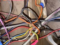
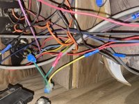
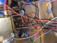
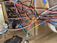
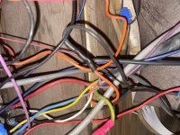
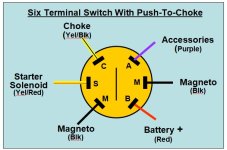
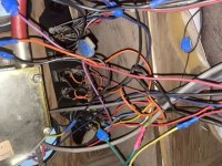
I have an 88 suntracker bass buggy, it had a 35hp force on it, we upgraded to 60Hp mercury from the same year. I am re-wiring everything, i have all the accessories done, and on one battery I want to setup the ignition system on a separate battery. As of now the boat runs drives and all, but before i tear apart the wiring i want to be sure i know what goes where, the only gauge that works so far is the voltage. The wires coming from the engine wiring into the console are orange, white, green, light blue, yellow, red, purple, The red is 12+ and plugged into the ignition, the purple coming from there is connected to a grey and brown wire going to the tach, orange, kinda goes nowhere, light blue, white go to the ignition switch, there is another purple (separate from the one coming from engine, which i believe is 12V+ ignition. into the ignition are red, white, green, light blue, purple, and yellow. No wiring diagram i find has these wire colors, i tried Merc and Force from those years. I had a shop install the bigger motor. If you can help me identify these wires and what they are i would greatly appreciate it, i am sure if i get this in order the gauges will work. My ignition is a 6 blade with push to choke. I have attached photos of the wiring to see if any help can be given. Thanks in advance.
 

Jasindude1

Cadet
Joined
Sep 4, 2020
Messages
20
4B8F42F7-C509-4EBE-A631-08B7409F1247.jpeg
 

Attachments

  • BE499B77-BAEF-4A31-BFA5-77781E99B6F7.jpeg
    BE499B77-BAEF-4A31-BFA5-77781E99B6F7.jpeg
    134 KB · Views: 8
  • 5A834E00-4116-43E4-865A-561BFF1680C6.jpeg
    5A834E00-4116-43E4-865A-561BFF1680C6.jpeg
    134.9 KB · Views: 10
  • 18D7548A-D8DC-4231-985E-D4F5E9061E3E.jpeg
    18D7548A-D8DC-4231-985E-D4F5E9061E3E.jpeg
    136.1 KB · Views: 10
  • 5F44B67B-C9AA-4AE4-B4A8-0666E7B90EB9.jpeg
    5F44B67B-C9AA-4AE4-B4A8-0666E7B90EB9.jpeg
    136.5 KB · Views: 10

jlh3rd

Chief Petty Officer
Joined
Jul 10, 2017
Messages
564
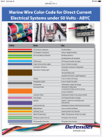
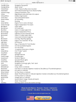
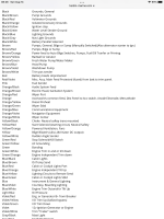
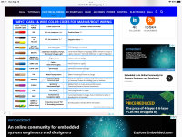
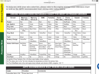
a rats nest, for sure.....so, if it was my boat, I'd start with using these marine color guides.....sort out what I have as correct.....and re-wire as needed...
 

Attachments

  • 4EB7DB86-1E1E-4FD1-A6CE-95B7EC0FF326.png
    4EB7DB86-1E1E-4FD1-A6CE-95B7EC0FF326.png
    1.5 MB · Views: 11
  • 1A401B63-0A73-47C3-8230-82A8DA1C451B.png
    1A401B63-0A73-47C3-8230-82A8DA1C451B.png
    1.3 MB · Views: 10
  • 586A1400-6E39-46D8-83DB-0A8D2AD977C7.png
    586A1400-6E39-46D8-83DB-0A8D2AD977C7.png
    470.6 KB · Views: 8
  • DE778AB2-FBAA-496C-8672-EEC47915DA1C.png
    DE778AB2-FBAA-496C-8672-EEC47915DA1C.png
    1.8 MB · Views: 10

jlh3rd

Chief Petty Officer
Joined
Jul 10, 2017
Messages
564
it can be ...frustrating to sort out for sure. I cleaned up the wiring on my '07 pontoon boat last year and even being wired correctly it was still a lot of work just to clean up the factory job....patience needed...

honestly....looking closer at your pics....all the splices and different colored wires connected randomly to each other?.....would drive me nuts.........
 
Last edited:

jlh3rd

Chief Petty Officer
Joined
Jul 10, 2017
Messages
564
you have two different threads on the same subject , you should keep them in one thread....
 

Silvertip

Supreme Mariner
Joined
Sep 22, 2003
Messages
28,771
Your pictures are not much help. Think about splicing and mixing wire colors on the same circuit. We can't see either end of this nest so you need to locate the wiring diagram for your specific engine (year & HP). The other end (the console end) is not done by the engine manfuacturer but by the boat manufacturer and they did not employ "artists" when they wired boats. But -- here are some tips. All of the gauges need a positive and negative 12 volt connection to them and the terminals are usually marked on the back of the gauge. The positive connection originates at the ignition switch so the gauges come to life when the key is on. The power connections are normally daisy chained (jumped) from one gauge to the next so get the first one in the string working and the others will likely work. Fuel gauge has an "S" terminal (sender) which should have a pink wire on it going directly to the sender in the fuel tank. Volt gauge needs no sender. Trim has an "S" terminal that connects to the trim sender on your engine. Tach "S" terminal usually has a grey wire on it that connects to the ignition system at the throttle/shift box. The speedometer is water pressure/air driven via a pitot at the back of the boat. No other sender used. Important: Take pictures NOW. Then work on ONE item at a time rather than dynamiting the whole works and creating a new set of problems.
 

froggy1150

Master Chief Petty Officer
Joined
Nov 3, 2017
Messages
846
Also to help verify. Get a volt meter and some long jumper wires. put on continuity with beep enabled and as you figure these circuits out you can test them.battery disconnected. IE..... for temp sender unplug from sender unit on motor and run jumper to helm. check wires til it beeps. Meter should also read dead short. 0.0-0.3. If it reads higher resistance you probably have a bad splice. After you have it all figured out redo everything as clean as possible.
 

Jasindude1

Cadet
Joined
Sep 4, 2020
Messages
20
well the wiring diagram I have for my year and make of boat doesnt have these colors, the engine manual doesnt have the same colors, both say grey is the tach, but of course there is no grey coming out of the wires, Im trying to really figure out the sequence of the ignition and what wires go where, the yellow i think goes to the solenoid and maybe the green is push to choke, who ever did this certainly did care about wire coloring, i have all sorts of different colors going into different colors. Also which wire connects to the tach? is it the stator? what gives me the pulses for the engine rpm reading?
 

jlh3rd

Chief Petty Officer
Joined
Jul 10, 2017
Messages
564
using the charts I sent and assuming you are correct that there are NO more wires coming from the engine/battery areas....
orange - generator output..
white - general alarm...I'm guessing engine computer alarm....also yamaha
kill switch.....but is questionable in your case...confusing....
green - grounding/ bonding for the individual circuits...then connected to
the main (yellow) or (black) ground
light blue- oil pressure
yellow - main ground..may also be black.
red - battery (positive)
purple (violet) - from ignition switch to: engine coils ( to fire the plugs), to
power electrical instruments such as voltmeter, tach( is not the
signal, just power), it would send power to my GPS speedo
which is NOT a mechanical speedo. A mechanical speedo does
not need this wire. It does need the blue (dark blue) wire for
backlighting.

I get the confusion. I have all my paperwork for my boat but there is no wiring diagram for my boat. I had to figure it out for myself.....
My original tach had 4 wires. ...purple for power....blue for backlighting...black for ground....grey for tach signal....I don't know why there is not a grey for you. I'm guessing it would be orange for you.
My fuel gauge has: black, blue, purple (all explained)...and pink (from fuel
sender).
My trim gauge has: black, blue, purple....
and brown with white stripe (trim position)...
My voltmeter has: black, blue, and purple.....

manufacturers especially back in 1988 do not necessarily follow standard wire colors.
I'm not an expert and hope this provides more pieces to your puzzle ....

as someone suggested, you need a multimeter so you can test your wiring for the circuit it is on..
 

Jasindude1

Cadet
Joined
Sep 4, 2020
Messages
20
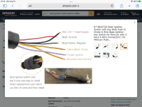
I’m re-wiring my pontoon, got all the accessories wired and ready to go, now it’s time to work on the gauges and ignition system, it’s a total mess inside my console! No real wiring diagram, I looked up my bot and engine and the wiring guide I got has wires I don’t even have. So anyways. This part is in my console, it has a wire coming from the key switch to an orange wire from the engine wiring. Any idea what this is? Trying to track down one part at a time. The part I need to know is the 1st photo. The 2nd is the mess I’m working with. I’m trying to do 1 at a time I don’t want my boat to become inoperable bc we go to the lake every week.
 

Attachments

  • 47BF1A60-8EAD-4412-BCB2-E41B4BDB33B1.jpeg
    47BF1A60-8EAD-4412-BCB2-E41B4BDB33B1.jpeg
    92.6 KB · Views: 9
  • 5EAD5074-DA82-41F3-B9E9-F5F4027D6C55.jpeg
    5EAD5074-DA82-41F3-B9E9-F5F4027D6C55.jpeg
    134.9 KB · Views: 9

froggy1150

Master Chief Petty Officer
Joined
Nov 3, 2017
Messages
846
See if you can verify wire colors at the drive. Maybe they were spliced along the gunwales somewhere
 

Jasindude1

Cadet
Joined
Sep 4, 2020
Messages
20
So i have a 1988 bass buggy, with a 88 mercury 60hp engine, not original engine, original was 1988 35 force. I just figured out i have US marine controls, they were re-used from the force motor, I got deep in forums and realized some of my wires but couldn't find the diagram or color coding. Red-power, black-ground, orange- overheat buzzer, purple-tach, I still have green, yellow, white and light blue to identify, white, green, yellow and light blue go to the key switch, does anyone know or familiar with this wiring scheme? I cant seem to find this ANYWHERE the manuals for the original engine and new engine all have totally different wire colors like grey to tach. If some one can help me sort out this mess, i cant post photos yet.thanks in advance for ur help
 

jlh3rd

Chief Petty Officer
Joined
Jul 10, 2017
Messages
564
this may help...
 

Attachments

  • 4025F448-95B2-4D90-A853-254005A510FB.png
    4025F448-95B2-4D90-A853-254005A510FB.png
    1.4 MB · Views: 14

Chris1956

Supreme Mariner
Joined
Mar 25, 2004
Messages
27,916
US Marine should have instruction on their web site, I would presume. Does maxrules have any wiring diagrams for the Force Motor? They will have one for the Merc.

OK, you can narrow it down. Tach will not go to the ign switch, but ign power will. The ign switch will also have starter solenoid, choke and ign killer.

So the ign switch will have +12VDC power, ign power out, choke, ground, ign killer and starter solenoid, for 6 wires. Starter solenoid will go thru an inline neutral safety switch, located in the control, then to the solenoid.

The harness will also have tach signal and overheat. Overheat wire is usually grounded when engine overheats. It will go to some buzzer in the control or under the dashboard. The tach signal will go directly to the tach, thru some external connector, along with ground and ign power.

The other choices for wires are trim/tilt sensor, trim/tilt wires usually green and blue.

Not sure if it helps.
 

Chris1956

Supreme Mariner
Joined
Mar 25, 2004
Messages
27,916
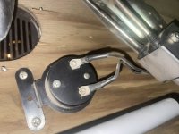
The black box could be an overheat buzzer. It is near a grating. Is that for the horn?
 

jbcurt00

Moderator
Staff member
Joined
Oct 25, 2011
Messages
25,047
All 3 wiring topics merged

Don't start duplicate topics about the same subject
 

jlh3rd

Chief Petty Officer
Joined
Jul 10, 2017
Messages
564
hard for us to do, not being there..
So i have a 1988 bass buggy, with a 88 mercury 60hp engine, not original engine, original was 1988 35 force. I just figured out i have US marine controls, they were re-used from the force motor, I got deep in forums and realized some of my wires but couldn't find the diagram or color coding. Red-power, black-ground, orange- overheat buzzer, purple-tach, I still have green, yellow, white and light blue to identify, white, green, yellow and light blue go to the key switch, does anyone know or familiar with this wiring scheme? I cant seem to find this ANYWHERE the manuals for the original engine and new engine all have totally different wire colors like grey to tach. If some one can help me sort out this mess, i cant post photos yet.thanks in advance for ur help
ok....does this help?...
green...choke
yellow....engine start
white.....stop
light blue......stator/cdi ?...see after 1994 ?
 

Attachments

  • 4D3323AE-5D70-4427-8CEC-295FC5791969.png
    4D3323AE-5D70-4427-8CEC-295FC5791969.png
    712.7 KB · Views: 16
Last edited:

jlh3rd

Chief Petty Officer
Joined
Jul 10, 2017
Messages
564
so....in my mind....
red comes from your harness to the ign. switch for switch power.
....that leaves 5 remaining switch terminals
4 terminals are used for: eng. start....eng. stop....choke....stator/cdi..
......that leaves one terminal left....
that terminal is for key on, power to instruments needing power....
.....now....
that leaves two wires coming from the harness...purple and orange...they do not go to the key switch....
....the purple connects and is the signal (not the power) for the tach...
.....the orange is overheat/engine warning (whatever)....goes to your buzzer, the "black" box you found....

my guess...
this does leave backlighting for the instruments unaccounted for....I believe my backlighting wiring comes from my navigation light switch.......??
and the switch ground wire ?...if that's what it's for ?

I'd like to see a good pic of the back of your switch...
 
Last edited:

Silvertip

Supreme Mariner
Joined
Sep 22, 2003
Messages
28,771
The ground wire on the switch is NOT to be used as a ground for any accessories. It is merely a ground for the internal light in the switch and the only thing it should be attached to or attached to it is the negative side of the battery.. As for the tach wire, you need to remember that the boat manufacture and engine manufacturer do not talk to each other over wiring. The tach wire you are looking for comes from the engine harness. Look at the shift/throttle control box for a three pin connector. That is the connection for a tach as well. If the grey wire from the engine harness is located, connect it to the "S" terminal on the tach. Otherwise obtain the tach harness from the dealer and connect it to the control box.
 
Top