Which one is Best ?

Sea Rider

Supreme Mariner
Joined
Sep 20, 2008
Messages
12,345
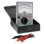
To measure overall Ohm and DVA output values while troubleshooting electrical componets such as : exciter, ignition coils and CDI outputs which meter is best to use an Analog or a Digital multimeter ?

Happy Boating
 

sam am I

Commander
Joined
Jun 26, 2013
Messages
2,169
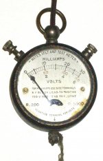
1920s_multimeter_3738-6b.jpg


LOL............

Digital with "peak min/max" feature is my go to hands down....But, I don't work on boat engines for a living, just as a hobby HOWEVER, I have slept, ate and lived with electronics and electronic test equipment almost my entire life because I have no life.

Analog meters have their place as some prefer that they instantly react to changes however, they can "load" the circuits under test and aren't as accurate. Digital is so dang fast these days, so accurate and durable, it's a moot point IME(experience).

 
Last edited:

Faztbullet

Supreme Mariner
Joined
Mar 2, 2008
Messages
15,902
Yes digital is good but there is no maker of a digital meter with built in DVA option, have to purchase adapter module seperate. I use several brands in my regular employment... the UEI for microamps (flame rectification) Fluke with scope to test VSD equipment, and Fieldpiece for every day 240/480V work.
 

sam am I

Commander
Joined
Jun 26, 2013
Messages
2,169
Last edited:

Sea Rider

Supreme Mariner
Joined
Sep 20, 2008
Messages
12,345
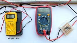
Know the Electronic Specialist multimeters well, the one shown is DVA capable which it's an outstanding characteristic. Was going for one, but as needed to troubleshoot electrical components real fast ordered a cheap one which does its homework pretty well. The oldie shown at left was far superior but stopped working some moons back, remains permanently at OL. What does OL stands for, is the meter repairable or has already entered kaput territory ?

Digital Multimeters.JPG

Technical Inquiry :
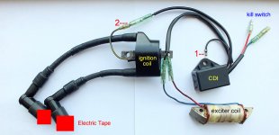
(1) If need to measure the CDI-DVA output while cranking the motor,the terminal 2 must always be connected to the ignition coil (2) terminal, if not risk screwing the CDI internally. Is it a true or false statement ?

Main Electrical Components.JPG

(2) If need to measure the exciter coil and CDI output while cranking with removed spark plugs for the pistons to achieve the min possible compression, must the plug's booths be taped as a precaution to avoid arcing if any ?

Happy Boating
 

Faztbullet

Supreme Mariner
Joined
Mar 2, 2008
Messages
15,902
Technical Inquiry :
(1) If need to measure the CDI-DVA output while cranking the motor,the terminal 2 must always be connected to the ignition coil (2) terminal, if not risk screwing the CDI internally. Is it a true or false statement ?
As long as meter is attached it will not damage CDI as meter completes the circuit. Also DVA needs to be tested when running to see if you drop voltage .You can also use a good induction timing light on this wire to see if you have intermittent output from CDI.

"(2) If need to measure the exciter coil and CDI output while cranking with removed spark plugs for the pistons to achieve the min possible compression, must the plug's booths be taped as a precaution to avoid arcing if any ?"
You measure the exciter output to CDI as this is AC voltage. The CDI unit has a internal rectifier to convert to DC for output to coil. On the wires either ground them, tape or move them so they cannot ignite any possible F/A mixtures blown from cylinders.
 

sam am I

Commander
Joined
Jun 26, 2013
Messages
2,169
SAM,
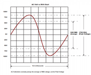
This is AC wave off a stator..
View attachment 336211
Looks reasonable, but since it's actually 170Vpp (not Vp) migrating equally above and below ground(0V), the DVA referenced to ground would measure 84.4Vp.

Recall a DVA circuit has a simple rectifier(current only flows one way) with a charge storage cap, thus the cap can only charge up to just the positive peak minus 0.6V(diode junction).

The *meter(set to DC) simply displays highest value the cap charged up to and is holding..... 85Vp - 0.6V = 84.4Vp.

The peak event/s (positive peak and negative peak) in your example are 8.3mS in duration ea. and are well within the flukes "peak min/max" spec of capturing events of 250uS or greater......The fluke set to "peak min/max" would then also display **85Vp.

Additionally regarding the example waveform in #7..........***Vrms = 0.707 * Vp, therefor 85Vp*0.707 = 60.095Vrms, not 120Vrms as incorrectly indicated .

*built in DVA(your example in #2) or external adapter.
** because the fluke uses a precision rectifier, there is no 0.6V diode drop.
***Concider the AC waveformin our houses.....170Vp * 0.707 = 120Vrms, not 240Vrms (see #5 youtube vid)
 
Last edited:
Top