Weird Battery Switch Wiring

Frizbal

Cadet
Joined
Jul 26, 2018
Messages
19
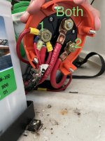
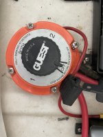
Went to do some wiring upgrades on the boat I bought a while ago and pulled the battery switch up. The wiring looks to be installed wrong, although somehow still functioning normally.
1 terminal: All accessories and motor connected
2 terminal: battery 2 connected
“Both” terminal: Battery 1 connected

From what I can tell, everything charges as it should, and I can still isolate each battery as if battery 1 and 2 were connected on the appropriate terminals.
This make sense to anyone? When I switch to Battery 2 in this configuration, shouldn’t I lose all of my accessories and only have two batteries powering nothing?
 

Attachments

  • C6B573F0-DF84-4BAC-B46F-F9CC4FC9CDC9.jpeg
    C6B573F0-DF84-4BAC-B46F-F9CC4FC9CDC9.jpeg
    648.9 KB · Views: 13

dingbat

Supreme Mariner
Joined
Nov 20, 2001
Messages
16,153
Went to do some wiring upgrades on the boat I bought a while ago and pulled the battery switch up. The wiring looks to be installed wrong, although somehow still functioning normally.
1 terminal: All accessories and motor connected
2 terminal: battery 2 connected
“Both” terminal: Battery 1 connected

From what I can tell, everything charges as it should, and I can still isolate each battery as if battery 1 and 2 were connected on the appropriate terminals.
This make sense to anyone? When I switch to Battery 2 in this configuration, shouldn’t I lose all of my accessories and only have two batteries powering nothing?
There is no “both” terminal per say.

The switch has a connection for each battery terminal and a connection for the starter/accessories. Perhaps the starter connection is labeled both

https://www.perko.com/images/catalog/pdf/Fig 8511-8512 Inst.pdf
 
Last edited:

poconojoe

Lieutenant Commander
Joined
Sep 10, 2010
Messages
1,966
Are you sure when you say everything is charging properly?
It doesn't seem to make sense to me either.

Maybe the physical "appearance" of the terminal locations may be different than their actual electrical relationships. How else would it function properly?

Terminal #1 for battery #1, terminal #2 for battery #2, third terminal is "common".

If it's all working fine, why have you questioned it?

Check out Perko's website for proper installation. They have several diagrams for different applications/situations.
 
Last edited:

Frizbal

Cadet
Joined
Jul 26, 2018
Messages
19
Are you sure when you say everything is charging properly?
It doesn't seem to make sense to me either.

Maybe the physical "appearance" of the terminal locations may be different than their actual electrical relationships. How else would it function properly?

Terminal #1 for battery #1, terminal #2 for battery #2, third terminal is "common".

If it's all working fine, why have you questioned it?

Check out Perko's website for proper installation. They have several diagrams for different applications/situations.
I was going in to install a bus to remove the multiple connections for all the accessories. Only questioned it because when I reinstall terminals, my mind tells me to “fix it” even though it seems to be operating correctly.
I haven’t hooked up an ammeter or anything, but using my digital gauges and watching battery voltage when applying a battery charger to each battery separately, it seems to be all correct. Maybe the switch labels are off…
 

dingbat

Supreme Mariner
Joined
Nov 20, 2001
Messages
16,153
Can’t assume terminals aligned or named in accordance with the nomenclature on the front of the switch. Terminal ID is embossed in the plastic by the terminal

The installation manual shows the terminals labeled as Feed, B1 and B2.

Looking closely at the photo, there looks to be B/2 embossed in the plastic underneath the terminal you identified as “Both”. If this is the case, the switch is wired correctly
 
Last edited:

Frizbal

Cadet
Joined
Jul 26, 2018
Messages
19
Can’t assume terminals aligned or named in accordance with the nomenclature on the front of the switch. Terminal ID is embossed in the plastic by the terminal

The installation manual shows the terminals labeled as Feed, B1 and B2.

Looking closely at the photo, there looks to be B/2 embossed in the plastic underneath the terminal you identified as “Both”. If this is the case, the switch is wired correctly
Ah ha! I get what you’re saying, and now that makes sense. Intuitively, one would think that the topside and the bottom side would (or should) match up. But you’re right, now that I’m looking at it, they don’t.
Thanks for the comment, glad I didn’t re-wire them to what I thought “looked right.”
 

poconojoe

Lieutenant Commander
Joined
Sep 10, 2010
Messages
1,966
Ah ha! I get what you’re saying, and now that makes sense. Intuitively, one would think that the topside and the bottom side would (or should) match up. But you’re right, now that I’m looking at it, they don’t.
Thanks for the comment, glad I didn’t re-wire them to what I thought “looked right.”
This was what I was trying to say in post #3. Maybe I didn't get the point across clearly.
Without actually testing it, you won't know for sure which terminal is which.
But... now we know it is embossed in the plastic in the back which wasn't evident in the photos. No doubt now which terminal is which.
 

poconojoe

Lieutenant Commander
Joined
Sep 10, 2010
Messages
1,966
Oh, good that you were looking to add a terminal block for those abundant wires on that one terminal.
I was going to suggest that, but didn't want to confuse things more. I figured get the problem at hand fixed first, which seemed more important.

On a good note: everything looks nice and clean. No corrosion. That's a plus!
 
Top