volvo penta - no click/no start

RoyalFlush67

Cadet
Joined
Jun 16, 2020
Messages
12
I have a no-click/no-start situation on my 99 Volvo Penta 5.0 GL. If I jump start red/yellow wire on starter solenoid to the positive battery post, boat starts great. I'm not getting any power to this wire when I crank the boat (0 volts). I've tested the start relay using Don S' HOW TO: Troubleshooting your engines starting system. Every test passed. Instead of using a test light, I used my voltmeter. Results are as follows:

1. 86 connection for relay to boat ground - 12 volts when cranking. 55 volts when not cranking. this is odd because on the next tests I got a full 12.7 volts, but not sure if this is normal.
2. 30 connection for relay to boat ground - 12.7 volts.
3. 30 and 85 connections for relay - 12.7 volts
4. tried jumping 30 to 87 at relay connections and boat did not start
5. Installed new relay with no luck

Thinking connection between relay and starter solenoid may be bad. Is it worth running a new wire from the relay to the starter solenoid? Not sure how wires hook into the relay connector though and need to verify in a wiring diagram that this is a straight connection (believe it is).

Here are some additional tests I've run and some other odd behavior:

1. Yellow/red at ignition key switch is only showing about 10 volts when trying to crank which is really odd. If I disconnect/pull the kill safety switch, voltage jumps back up to 12+ volts. replaced ignition key switch and this didn't change anything.
2. Tested for voltage drop between negative battery post and engine connection. drop was .4 volts. this seems high for a 2-3 foot 4-6 gauge wire but not sure how this could be causing a complete loss of voltage at the red/yellow wire on the starter solenoid. I would have already replaced this cable as a troubleshooting test, but it's going to be very difficult for me to disconnect the cable from the engine based on where it connects and a wire connector that is in the way of the nut that I will have to cut off.

Any thoughts would be appreciated. I'm close to bringing it to the mechanic I use for difficult repairs, but this is typically a 3 week wait in the middle of the summer.
 

alldodge

Moderator
Staff member
Joined
Mar 8, 2009
Messages
42,056
Which GL model?

The .4V should happen because there is a diode inline

Pins 85 and 86 is the relay coil

Pins 30 (in) and 87 (out) is relay contacts

Pin 85 should be ground

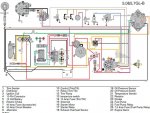
This is a GL-B
VP wiring GL_B.jpg
 

alldodge

Moderator
Staff member
Joined
Mar 8, 2009
Messages
42,056
Was looking for a GL A, B C or D, E

Its my understanding your talking about the start assist relay. The relay has a Red ad Yellow/Red (30 to 87) connection. If those are jumped across, this should engage the starter.

With the other voltage variations your seeing, remove the battery cables at both ends, including the ground on the block side. Make the metal is nice and shinny
 

RoyalFlush67

Cadet
Joined
Jun 16, 2020
Messages
12
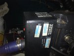
Yes. referring to the start relay (#17 in diagram) above. 30 and 87 are the connections I jumped where the relay plugs in, but the starter does not engage. It does engage when I jump at starter solenoid. I do believe my model is a PWTR vs A, B, C, D or E, although I'm not 100% sure. See the attached tag from my engine. Not sure how many of these they made.

I can pull and clean all positive and negative battery cable connections. Disconnecting the negative at the block will be a big project which is one of the reasons I posted here before I got into this project and possibly down the wrong path.

Thanks again for reviewing.
 

Attachments

  • photo332767.jpg
    photo332767.jpg
    677.8 KB · Views: 10

alldodge

Moderator
Staff member
Joined
Mar 8, 2009
Messages
42,056
Maybe muc can help explain it to me

I have diagrams for GL A, thru E and not which list PWTR (Power steering, 1998-1999, R service code)

In any case sine were talking about the Assist Relay (AR), it should be easy enough.

Motor will start by jumping the small inboard post on the solenoid to the main battery post. Doing this is the same as when the AR sends power down the larger Yellow/Red wire to the inboard small terminal.

To energize the AR power comes from the key, thru the neutral safety to the coil of the AR.

Yes. referring to the start relay (#17 in diagram) above. 30 and 87 are the connections I jumped where the relay plugs in, but the starter does not engage. It does engage when I jump at starter solenoid.

This means the Yellow/Red wire going from pin 87 to the small inboard solenoid connection has a break in it. The break is in the wire or the connection points
 

RoyalFlush67

Cadet
Joined
Jun 16, 2020
Messages
12
Thanks for reviewing alldodge . I'll test yellow/red wire connections at pin 87 on AR and starter solenoid, and run a new wire as needed. Suspect I may have a ground issue too. Negative battery cable doesn't look great. The clamp is permanently attached to negative cable (not the screw down type clamps) and there is more play between cable and clamp than I think is good.
 

muc

"Retired" Association of Marine Technicians...
Joined
Jul 7, 2004
Messages
2,143
Without the serial number, I can't make sure you have the correct wiring diagram. Sometimes with something this old, I can't pull up a diagram even with the serial number.

Assuming the diagram alldodge posted is correct.

No diode on the negative side. But 0.4 volts drop isn't enough to cause this problem.

First make sure you have the right relay. Is it possible your're doing these tests on the fuel pump relay? Most of the wires are the same color.

No click when you turn the key to start is important. This tells me you don't have battery power at the yellow/red going to 85 or you don't have a good ground at the black going to 86. Or the relay is bad. It can ONLY be those 3 things.

Sometimes when your using a volt meter it's possible to get the wrong readings. Like, take for example the yellow/red going to 85. If that wire is mostly broken somewhere and only has one tiny strand of wire making a connection. Your volt meter will read good voltage, but when there is a load on the system. Not enough voltage will get thru that tiny wire. That's why a test light is the recommended tool to use. Especially one that draws at least one amp of power.
 

RoyalFlush67

Cadet
Joined
Jun 16, 2020
Messages
12
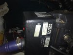
Great info muc . I've attached my serial number. I wasn't aware of why a test light is recommended. I'll go and buy one. my old test light is no longer working.

The relay I tested and replaced could very well be the fuel pump relay. It is siting in from of my fuel pump. The relay is part # 586224. It has all the same connections as the starter relay I believe which are 85, 86, 30, 87 and 87a and that is why I thought it was the starter relay. If this is the fuel pump relay, I now have no idea where my starter relay. I can keep hunting, but just looked and didn't see another relay.
 

Attachments

  • photo332805.jpg
    photo332805.jpg
    605.2 KB · Views: 9

RoyalFlush67

Cadet
Joined
Jun 16, 2020
Messages
12
Just found this engine harness wiring diagram. I'm pretty sure I tested the fuel pump relay. This should help me locate the starter relay, but any suggestions on locating it would be appreciated.
 

muc

"Retired" Association of Marine Technicians...
Joined
Jul 7, 2004
Messages
2,143
It will be in the black box where the main circuit breaker and the main harness plugs in -------- the black box in your picture.

edit: unable to pull up wiring diagram. Did find diagram for the next year newer. Same as alldodge posted. Check the blade type fuse in box. I think the starter slave relay is the same as fuel pump relay, so you can swap them.
 
Last edited:

RoyalFlush67

Cadet
Joined
Jun 16, 2020
Messages
12
thanks muc for letting me know where the starter relay is located. if the relays are the same, that will be nice. are you saying to check the regular blade fuses in my main fuse box too? I believe this is what you are saying.
 

muc

"Retired" Association of Marine Technicians...
Joined
Jul 7, 2004
Messages
2,143
It never hurts to unplug and replug the fuses in the main box to clean the connections. But the fuse I was talking about is in the black box.
 

RoyalFlush67

Cadet
Joined
Jun 16, 2020
Messages
12
It was a little bit challenging getting the relay unplugged (it clips in on one side and is held in place tightly based on how the base is created), but did it off and then jumped 30 to 87 on the starter relay and the starter turned over. This was great news! Getting a new relay tomorrow and hope that fixes everything. It will definitely get the boat starting properly again, but will have to see if the lower voltage at the key switch when turned to on is fixed. I know I'm getting full voltage to the ignition key switch and it only drop when I switch the key switch to on, so hoping the relay resolves this too.
 

muc

"Retired" Association of Marine Technicians...
Joined
Jul 7, 2004
Messages
2,143
The symptom of a problem that is somewhere between battery positive and the back of your key switch. Is that you will have battery voltage at the key switch until you put a load (turn the key on) on it. If that voltage drops more than one volt, you have a problem.
 

muc

"Retired" Association of Marine Technicians...
Joined
Jul 7, 2004
Messages
2,143
It was a little bit challenging getting the relay unplugged (it clips in on one side and is held in place tightly based on how the base is created), but did it off and then jumped 30 to 87 on the starter relay and the starter turned over. This was great news! Getting a new relay tomorrow and hope that fixes everything. It will definitely get the boat starting properly again, but will have to see if the lower voltage at the key switch when turned to on is fixed. I know I'm getting full voltage to the ignition key switch and it only drop when I switch the key switch to on, so hoping the relay resolves this too.

Replacing the relay won’t help with a voltage drop at the key switch.
 

RoyalFlush67

Cadet
Joined
Jun 16, 2020
Messages
12
The new starter relay fixed my starting issue. Boat cranks perfectly. Now on to trying to figure out my voltage drop issue. You were spot on muc . Relay didn't help that at all.
 

muc

"Retired" Association of Marine Technicians...
Joined
Jul 7, 2004
Messages
2,143
glad you got the cranking issue taken care of, good luck with the voltage drop.

Thanks for the update.
 

RoyalFlush67

Cadet
Joined
Jun 16, 2020
Messages
12
I've found at least 1 volt of the approximate 2 volt drop I am seeing at the ignition switch when I turn on the key. when I first tested the voltage at the key switch today, it was 10.7 volts with the key switch on. By disconnecting, reconnecting and holding the positive ignition wire at the fuse box, I can get a 11.5 reading at the key switch which is just over 1 volt drop from the 12.6+ reading at the fuse box itself. This is slightly more than the 1 volt acceptable drop you mention. I believe if I can clean the male connector at the box and put a new wire connector on the wire this may fix it completely or at least get within spec. Unfortunately the wire at the fuse box is not long enough to put on a new connector, so I would have to use a butt connector to extend the wire length.

muc or anyone else do you know if the power ignition wire coming from the fuse box runs directly to the key switch B (battery / power source) connection? there is only a short distance from the fuse box to the key switch, but I can't tell if this is how the wire is run. there are just too many wires and connectors in the area. If this wire simply runs from the fuse box to the key switch, I would prefer to just run a new wire as opposed to extending existing wire.

it took me a half dozen tests to find this one drop but I think this may be the sole issue or at least a significant part of the drop.
 

alldodge

Moderator
Staff member
Joined
Mar 8, 2009
Messages
42,056
Power comes from the engine connector plug (red/purple) to a ignition fuse then to the key. If the Red/purple comes from the ignition fuse to the key, that is the feed
 
Top