Volvo Penta 5.7 GSI

continental1971

Seaman Apprentice
Joined
Jan 3, 2023
Messages
31
Good Morning
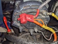
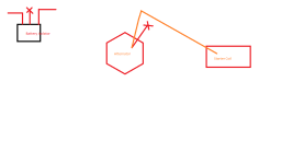
Someone cut some cables from the Alternator and I am trying to figure out where the red wire connects to. I think it goes to the battery, question should it go to the battery switch or directly to the battery? I have two batteries house and Starting battery. See the image below.

Thank You

Alonso
 

Attachments

  • PXL_20230120_010724482.jpg
    PXL_20230120_010724482.jpg
    3.1 MB · Views: 15
  • PXL_20230119_235937539.LS.mp4
    8.6 MB · Views: 2

cptbill

Senior Chief Petty Officer
Joined
Oct 6, 2012
Messages
732
I belive that the red wire goes to the poss. terminal on the starter with the red wire to the batt.
 

alldodge

Moderator
Staff member
Joined
Mar 8, 2009
Messages
40,581
As cptbill said the Orange wire should go direct to the starter post of which the main battery cables attaches to.

There should not be another Red wire also on it unless the orange was damaged. Where does the Red go to?
 

continental1971

Seaman Apprentice
Joined
Jan 3, 2023
Messages
31
Yes, I can confirm the orange wire is going to the starter. My question is the red wire that is cut... should it go directly to the battery or battery switch position 1? or 2? or parallel? Also if it goes to a battery switch, do I have to use a fuse, or does the battery switch already has one?

Thanks

Alonso
 

alldodge

Moderator
Staff member
Joined
Mar 8, 2009
Messages
40,581
The pic does not show that the Red is cut, but being cut, remove it and don't use it. It should not be there in the first place
 

continental1971

Seaman Apprentice
Joined
Jan 3, 2023
Messages
31
Thank you guys for quick responses and the help.....
Just one final question how does the alternator recharge the batteries??

Alonso
 

alldodge

Moderator
Staff member
Joined
Mar 8, 2009
Messages
40,581
Thank you guys for quick responses and the help.....
Just one final question how does the alternator recharge the batteries??

Alonso
We really need to understand how its wired?

This is the standard 1 Bat diagram for the GSI
Slide1.JPG

Can see the Orange wire going to the starter post. The ALT will send power to the post and this will feed back to the Bat

If you have a Start and House Bat then you will probably have a Bat switch. Once the motor is running the switch can be moved to ALL (BUT only if its a make-before-break switch), which most are. Then the ALT will charge both Bats at same time. There are issues with this but its simple setup

Can also wait to the boat returns to the dock and then shore power reconnected. Main Bat charger will charge all Bats.

Now you use a isolator or ACR to charge both Bats automatically once motor is running
 

continental1971

Seaman Apprentice
Joined
Jan 3, 2023
Messages
31
Alldodge

Yes starter red wire is to battery switch with an isolator so like you advice before I will remove the red wire and forget about it...

Thank you for your help.

Alonso
 

cptbill

Senior Chief Petty Officer
Joined
Oct 6, 2012
Messages
732
It seems to me that maybe someone tried to charge 2 batt. from the same alt. and that might work if it's the 95 or 110 amp alt. So if the red wire goes now where then take it off and make your charging system look like the diagram above
 

continental1971

Seaman Apprentice
Joined
Jan 3, 2023
Messages
31
Hello
Guys after tracing some wires I found out that the battery isolator is cut and it would appear that at one time it was connected o the starter or starter coil. The other two wires from the battery isolator are not connected to a battery switch but I have not traced where exactly they go yet. (it is cold in Indiana today). I have attached some pictures and a crude diagram of what wires are connected.

The questions I have... The red wire that is cut from the battery isolator should go to the starter coil or the red wire that is cut from the alternator?

Thank you in advance

Alonso
 

Attachments

  • PXL_20230121_205020728.jpg
    PXL_20230121_205020728.jpg
    3.1 MB · Views: 5
  • PXL_20230121_205110390.jpg
    PXL_20230121_205110390.jpg
    3 MB · Views: 5
  • PXL_20230121_205124890.jpg
    PXL_20230121_205124890.jpg
    2.2 MB · Views: 5
  • PXL_20230123_143102687.jpg
    PXL_20230123_143102687.jpg
    3 MB · Views: 4
  • Connection.png
    Connection.png
    9.7 KB · Views: 4

alldodge

Moderator
Staff member
Joined
Mar 8, 2009
Messages
40,581
First find out if the isolator has not shorted or opened up
Disconnect wires from isolator, set meter to "Diode check" and measure Common (most times center post) to one of the other post. With probes on one way the meter will read high and when probes are swapped it will read low. If low is read in both directions then diode is shorted, if high in both then its opened

Pic shows how isolator should be wired without a Battery switch and with a onboard Bat charger. If you do not have a on board charger then disregard the leads.

The Orange wire would be removed from starter post and attached to common post on isolator. Again a ACR would be better then isolator

Two Bat Isolater no switch.jpg
 

continental1971

Seaman Apprentice
Joined
Jan 3, 2023
Messages
31
Alldodge
O.k. I do have a battery charger so this diagram helps.... Just have one question out of curiosity... Why use the orange wire coming out of the alternator and not the red one to connect to the battery isolator?

Check the battery isolator and it is not open or shorted.

Thanks

Alonso
 
Last edited:

alldodge

Moderator
Staff member
Joined
Mar 8, 2009
Messages
40,581
Why use the orange wire coming out of the alternator and not the red one to connect to the battery isolator?
The standard wire coming from ALT to Starter post is Orange (original wire from Merc). The Red was added at a later time.

That said, you could disconnect orange at the ALT and run a new 10AWG wire from ALT to Isolator. Best to have 90 Amp Fuse/Breaker inline from ALT

Also disregard the sense lead in the drawing
 

Donald0039

Petty Officer 1st Class
Joined
Jun 11, 2022
Messages
324
Your typical alternator with internal regulator has 3 wires. Large one for output, two smaller ones, one switched by ignition for excite and one not switched by ignition for sense.
 
Top