Steve cason
Recruit
- Joined
- Jul 9, 2023
- Messages
- 4
Hi all.
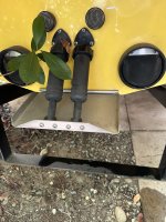
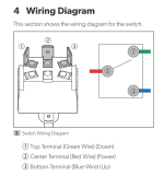
I have a Bennet trim tab hydrolic pump running the one trim tab in my centurion wake board boat. It is controlled by a Protrim blinker style switch.
I have had electrical gremlins in the boat that I was finally able to isolate to the trim motor. When it is unplugged (remove both ground and the 4 pin connector), everything works great in the boat. However, when it’s connected I get a significant voltage drop at the helm (on the boats voltage gauge as well as when measuring with multi meter at the fuse buss).
I figured that the problem was a bad pump, and replaced the pump. However the problem got worse…. In fact some of the wires in the helm are actually hot to the touch…. Seems to me to be a huge ground loop problem on the circuit controlling the pump.
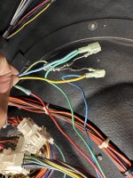
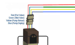
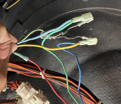
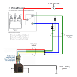
Between the blinker style Switch and the wires going to the pump, it was installed with 2 diodes so that the green wire is positive when either yellow or blue are. Logically, this is right… but I’m wondering what could be going wrong. Or if the diode method is right…
I have not yet checked continuity on the switch or voltage drops along that circuit…. That’s next..
Any help is appreciated.
See pictures.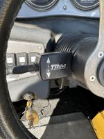


