Trim position sensor

rickasbury

Senior Chief Petty Officer
Joined
Jul 13, 2011
Messages
755
I am on a quest to have my trim work correctly. I worked through a helm switch issue, trim selonoid issue and now down to the trim sender and limit switch, bravo lll. Both sendors I replaced via another issue and the sender nver worked...
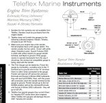
Found a good test for the system which starts with the sensor and an ohm test which I did and it failed. So, also in the instructions, which puzzled me at the time, was to remove the sendor and turn it by hand. It further said if it now passes, grease the hinge pin...I could not stretch that far- I did mark the hinge pin and raise the drive and the dam thing is turning with it! How can that be? 145 lbs of torque on it, not corroded..
 

alldodge

Moderator
Staff member
Joined
Mar 8, 2009
Messages
40,754
The hinge pin (inside part) does turn with the drive. The outer housing of the limit (outside part) and sender don't move when attached to gimbal ring
 

rickasbury

Senior Chief Petty Officer
Joined
Jul 13, 2011
Messages
755
The hinge pin (inside part) does turn with the drive. The outer housing of the limit (outside part) and sender don't move when attached to gimbal ring
I will have to go back to an asy drawing- I had it apart but that was a while ago. The part that is geared has to be stationary so as the the drive raises it turns the mating part of the sender? I marked it and it turn in step with the rest of the out drive..so is not turning the sender.
 

rickasbury

Senior Chief Petty Officer
Joined
Jul 13, 2011
Messages
755
I will have to go back to an asy drawing- I had it apart but that was a while ago. The part that is geared has to be stationary so as the the drive raises it turns the mating part of the sender? I marked it and it turn in step with the rest of the out drive..so is not turning the sender.
Answered my own question and it is doing what it is supposed to but not getting any ohm reading on it...and it was a new one. Might just have to live with it and make sure the limit switch is working.
 

alldodge

Moderator
Staff member
Joined
Mar 8, 2009
Messages
40,754
If the senders are installed correctly (sender starboard, switch port) and your getting no reading using just the 2 leads, then sender is bad. Do rotate it all around to make sure.

The switch will show a connection (zero ohms) until it opens
 

Chris1956

Supreme Mariner
Joined
Mar 25, 2004
Messages
27,158
Trim gauges are overrated. They react slowly to trim, and only give a rough approximate of the trim angle, which changes as the sender corrodes.

It is best to trim by sound and the feel of the steering. You will hear the trim motor sound different at full down and full up. All other trim angles are best based upon sound and feel, as conditions and boat loading have large influences on the ideal trim angle.

I pulled my trim gauge out and replaced it with a water pressure gauge. Much more important on an outboard. On your I/O I would expect your trim gauge to be a decoration, rather than a vital function.

On most boats, the prop ventilates, before you reach the trim limit switch open point.

If your trim sender is new and not working, suspect the wiring. If is exposed to the water on the outside of the boat and the bilge on the inside of the boat. Both can be hard on the copper conductor.
 

rickasbury

Senior Chief Petty Officer
Joined
Jul 13, 2011
Messages
755
Thanks Chris- I agree 100%. I for sure trim the motor and trim tabs by feel- if I look at any gauge it's rpm. But, I'd like it to work! I'd like to hit the key before I crank the motor and know where the drive is. And in shallow might get that drive up a little higher than wanted without cavitation at slow speed. Also if I put a for sale on it I want things to work.
 

rickasbury

Senior Chief Petty Officer
Joined
Jul 13, 2011
Messages
755
If the senders are installed correctly (sender starboard, switch port) and your getting no reading using just the 2 leads, then sender is bad. Do rotate it all around to make sure.

The switch will show a connection (zero ohms) until it opens
Thanks- I'm reading bits and pieces about these and may not have it straight.
On the sender, which right now is leaning to being bad (although it's new)- that is not an off/on switch like the limit switch right? It seems to only want to turn 180 degrees...if it does not appesr to work should I rotate it through that tight spot? I'm looking for a range of ohms numbers as it is rotated..

On the limit, I read somewhere it will turn on/off 2x in 360 degrees- have not looked at that side yet.
 

Chris1956

Supreme Mariner
Joined
Mar 25, 2004
Messages
27,158
If you replaced the trim limits and trim senders and it doesn't work, suspect the wiring. Both sender and limit were open to the water, which doesn't help.
IMO, the wiring had every chance to be pinched by the outdrive, and needed to pass thru the outdrive hull fitting to reach the dashboard. There were lots of places the wire could rub, corrode or just break.
 

rickasbury

Senior Chief Petty Officer
Joined
Jul 13, 2011
Messages
755
Thanks Chris. I will restate my questions...

Since I replaced the two senders it has not been in the water very much and I'm not costal- not that something did not get pinched installing the motor and outdrive. The sender seems to only want to turn 180 degrees and the operational angle of the trim is only like 30 degrees tops before it should hit the limit for the limit switch. Is the whole 360 degrees operational for the sender? If I'm not getting a reading on the ohms should I spin the gear on the sender past that point to find the working range? I can test again right at the sender but I hate to brake the wire covering that is under water. Guess I don't have anything to lose at this point.
 

alldodge

Moderator
Staff member
Joined
Mar 8, 2009
Messages
40,754
Thanks- I'm reading bits and pieces about these and may not have it straight.
On the sender, which right now is leaning to being bad (although it's new)- that is not an off/on switch like the limit switch right? It seems to only want to turn 180 degrees...if it does not appesr to work should I rotate it through that tight spot? I'm looking for a range of ohms numbers as it is rotated..

On the limit, I read somewhere it will turn on/off 2x in 360 degrees- have not looked at that side yet.
The senders "should" (I say should) have port/starboard on their sides

Both senders use the same wires so if your sure you have the wires for a given side, and the meter is connected on those same two wires, thenyou have a bad sender
 

rickasbury

Senior Chief Petty Officer
Joined
Jul 13, 2011
Messages
755
The senders "should" (I say should) have port/starboard on their sides

Both senders use the same wires so if your sure you have the wires for a given side, and the meter is connected on those same two wires, thenyou have a bad sender
The wires might look similar but ay least on mine, the connections are all different. I'll play with it a little more today and see if I can set the trim limit- and move on.. I'm not going to pull the drive to fix either. I did buy new ones when I did a transom repair but never got around to messing with them.
Thanks for the input. I've learned way more about this boat than I ever wanted to...
 

04fxdwgi25

Chief Petty Officer
Joined
Mar 25, 2022
Messages
446
Just a guess here. May have been installed on side of drive out of phase.

Since the trim sender has a square nub on it, it could have been rotated by mistake and can be placed out of phase into the hinge pin.

Put drive all the way down. Disconnect the trim sender from side of drive. Rotate the sender drive nub until it shows all the way down on the gauge. Insert into the hinge pin at that position and fine tune it from there.
 

rickasbury

Senior Chief Petty Officer
Joined
Jul 13, 2011
Messages
755
Just a guess here. May have been installed on side of drive out of phase.

Since the trim sender has a square nub on it, it could have been rotated by mistake and can be placed out of phase into the hinge pin.

Put drive all the way down. Disconnect the trim sender from side of drive. Rotate the sender drive nub until it shows all the way down on the gauge. Insert into the hinge pin at that position and fine tune it from there.
Thanks for the reply- I'm a bit beyond that as the Guage is not moving. With the ignition off it pegs high- when you turn the ignition on it drops slightly but still shows up regardless of the drive position. I did recheck ohms with the sender removed and did not get any ohms reading.

I also rechecked the limit switch and I get ohms on it but it never closes. These were both new mercruiser senders I put on when the transom was apart so a little disappointing...the up will only work with the jumper on the harness...I'm going to get it back together as is as the weather is awesome and missing some really good boating. Sounds like the position sender may be working and the problem being with the Guage back- another day I guess...
 

04fxdwgi25

Chief Petty Officer
Joined
Mar 25, 2022
Messages
446
I have included a few documents for your reading pleasure.
1st is Mercruiser sheet on replacement / test / adjust
2nd is the trim system / limit switch puck wiring
3rd is an exerpt from telflex on troubleshooting and adjusting trim indicator puck and gauge
 

Attachments

  • Trim Switch Replacement_Adjustment.pdf
    760.6 KB · Views: 10
  • Trim system wiring.jpg
    Trim system wiring.jpg
    115.8 KB · Views: 10
  • Trim position indicator repair.jpg
    Trim position indicator repair.jpg
    205.9 KB · Views: 10

QBhoy

Fleet Admiral
Joined
Mar 10, 2016
Messages
8,310
Hi. Not sure if it helps..but there is a measurement you need to take along the reach of the drive trim arms. Something like 22” or something similar…to help position the sender to a certain position. Then tiny adjustments to dial it in from there really. That’s if the sender itself is actually working in the first place.
 

rickasbury

Senior Chief Petty Officer
Joined
Jul 13, 2011
Messages
755
Hi. Not sure if it helps..but there is a measurement you need to take along the reach of the drive trim arms. Something like 22” or something similar…to help position the sender to a certain position. Then tiny adjustments to dial it in from there really. That’s if the sender itself is actually working in the first place.
The trim limit does not seem to be working..it is new...I jumped it. My trim working range is not that big anyway, I was just trying to get it to work since I did replace it when I pulled the motor....I'll get back to it again one day.
 

04fxdwgi25

Chief Petty Officer
Joined
Mar 25, 2022
Messages
446
Just went through this last week. Disconnect the limit wires inside the transom, behind the engine, and see if your trim up still works. If it does, there is a wiring problem somewhere, effectively bypassing the up limit. If it will not trim up, it is the puck on the drive.

The sender guts can be installed in any of 4 positions on the drive hinge pins. Take the cover off the puck and remove the contact arm. You should be able to see the contact pads on the puck base. Raise the drive to measure about 21.5 to 22" between the ram pivot shafts. Looking inside the puck, you can determine if the contact arm will be positioned correctly on the contact pads and go from there.
 

rickasbury

Senior Chief Petty Officer
Joined
Jul 13, 2011
Messages
755
Just went through this last week. Disconnect the limit wires inside the transom, behind the engine, and see if your trim up still works. If it does, there is a wiring problem somewhere, effectively bypassing the up limit. If it will not trim up, it is the puck on the drive.

The sender guts can be installed in any of 4 positions on the drive hinge pins. Take the cover off the puck and remove the contact arm. You should be able to see the contact pads on the puck base. Raise the drive to measure about 21.5 to 22" between the ram pivot shafts. Looking inside the puck, you can determine if the contact arm will be positioned correctly on the contact pads and go from there.
Interesting...I will check this out.
 
Top