Tricky Yamaha C85 Electrical Problem - 1 cyl OOS - Problem Rolls with Stator wires but new stator - Same issue

boscoe99

Lieutenant Commander
Joined
Aug 22, 2013
Messages
1,826
One pulser coil for two cylinders. The CPS for the other cylinder.

Reason why I brought up Excel is that when learning that program decades ago I found out there were many different ways to get to the same end result.

Similar to Yamaha using different ways to fire three cylinders.

I have said it a million times but it bears repeating IMO. A shame that Yamaha does not provide a theory of operation in each SM for each particular model.
 

99yam40

Fleet Admiral
Joined
Sep 7, 2008
Messages
8,891
Yea, my C40 has 3 pulsers coils one for each cylinder.
that makes more sense than all this other stuff added to mystify the way things work.

So if that C85 has 2 pulser coils should that mean #1 is run off of one and #3 run of the other, since swapping the brown and blue wire makes the miss move from #1 to #3 cylinder?
whick one fires #2?

I still have no idea what those wire actually come from.

Do You think his manual has a schematic that would show that info?
 
Last edited:

boscoe99

Lieutenant Commander
Joined
Aug 22, 2013
Messages
1,826
Some Yam six cylinder models have six pulser coils.

I have no idea what manual the OP is using. Seems that it is trying to do a better job with the theory of operation. What does what and when.
 

Havana

Cadet
Joined
Feb 12, 2023
Messages
7
Boscoe, you know anything about a C85 ingition system?
should it be the same as a 90 about that year?

99yam did you ever use the Excel program by Microsoft?

We could surely use rodbolt.
First off, I'd like to say thanks. You guys put in some time and thought into this so far and that is the most valuable resource we have.

To clarify, I have attached a few pictures of the stator and the pulser coil as well as the repair manual blurb about the unique dual firing from a single pulser coil as well as a simple CDI map.
On the CDI the stator normal charge connections are #1(Brown/Br) #2 (Blue/L) and #3 (Red/R) cylinders no fire on #1. I roll the connections on the CDI to #1(Red/R) #2 (Blue/L) and #3 (Brown/Br) and the problem moves down to the #3 cylinder essentially following the brown wire output from the stator. The problem is that this is the same behavior on 2 stators .

Read the blurb and see if you have seen this before. I have heard of some CDIs using the relationship of a coil to determine the position of an adjacent cylinder but I am not sure if this is what it it doing. Based on the manual think it actually is reading the direction of the current flow as the shift occurs on the single pulser. This is a SELOC manual, I also have the service manual for a C85 which gives specs for static checks ... all which pass.
Another thing... can either one of you tell me what the green wire is coming from the pulser? The pulser has 4 wires , 1 for each cylinder and another that lands into the opposite of the CDI but it doesnt say what it is for. Again.. Thanks for your time.
-Havana
 

Attachments

  • Stator Wires.jpeg
    Stator Wires.jpeg
    2.3 MB · Views: 2
  • Stator Wires 2.jpeg
    Stator Wires 2.jpeg
    3.6 MB · Views: 2
  • CDI Layout.jpeg
    CDI Layout.jpeg
    3.9 MB · Views: 3
  • 0BD8AA73-7303-4BE3-A40D-BA95DEBAD718.jpeg
    0BD8AA73-7303-4BE3-A40D-BA95DEBAD718.jpeg
    4.8 MB · Views: 3
  • Pulser Coil.jpeg
    Pulser Coil.jpeg
    692.1 KB · Views: 3
Last edited:

99yam40

Fleet Admiral
Joined
Sep 7, 2008
Messages
8,891
It would. lol

this drawing shows 4 wires for the pulser coils and 3 for the charge coils.
charge coils have a common between, but pulsers show totally separate from each other.
Does your manual show something like this with wire colors on those wires?

you said green wire, but I am sure you meant white with green stripe.

I still am not sure on this about the charge coils.
are they a low speed and high speed coils?
or do different cylinders use different chargeging coils?
very confusing
 
Last edited:

boscoe99

Lieutenant Commander
Joined
Aug 22, 2013
Messages
1,826
If all of the inputs to the CDI are within specifications, but the outputs from the CDI are not within specifications, the CDI is presumed to be defective.
 

99yam40

Fleet Admiral
Joined
Sep 7, 2008
Messages
8,891
This is good info.
I have a feeling the OP has not measured peak voltages, just ohmed out everything.
but I could be wrong.

still does not make sense why swapping the brown and blue wire on charge coils moves the miss from #1 to #3
I guess that would change the polarity maybe.
but I would have thought the pulser coil polarity would be where that changed to fire at correct time
 

Havana

Cadet
Joined
Feb 12, 2023
Messages
7
Boscoe , I wonder what would happen if I fed #1(brown) and #3(red) stator position on the CDI from the working red wire? Basically split the output from the red stator wire and run to the #1 and #3 pos on the CDI. The trigger appears to be working fine. If the current is high enough, the caps in the CDI should stay loaded and release during the trigger. Since the #2 middle stator CDI position actually takes a wire, I don't think the CDI does any type of calculatiaon to determine the correct firing position.

As I said, the stator ohms well on all branches and passes the test on AC power output on all branches. The same happens on two stators that appear good.

I'd appreciate your input before I do it. What do you think?

Havana
 

boscoe99

Lieutenant Commander
Joined
Aug 22, 2013
Messages
1,826
Boscoe , I wonder what would happen if I fed #1(brown) and #3(red) stator position on the CDI from the working red wire? Basically split the output from the red stator wire and run to the #1 and #3 pos on the CDI. The trigger appears to be working fine. If the current is high enough, the caps in the CDI should stay loaded and release during the trigger. Since the #2 middle stator CDI position actually takes a wire, I don't think the CDI does any type of calculatiaon to determine the correct firing position.

As I said, the stator ohms well on all branches and passes the test on AC power output on all branches. The same happens on two stators that appear good.

I'd appreciate your input before I do it. What do you think?

Havana
Can we stay with Yamaha terminology? I can not readily understand what you are saying.

There are the pulser coils and there are the charge coils.

I would not attempt to make the wire connections in any manner other than what is shown in the Yamaha service manual.

If you have the correct voltages from the charge coils to the CDI, and if you have the correct voltages from the pulser coils to the CDI, and the CDI does not provide the appropriate output to the ignition coils, then I would suspect that the CDI is defective.
 

Havana

Cadet
Joined
Feb 12, 2023
Messages
7
Update:
I used a DVA and tested all components. Now when I say volts,all the outputs of the stator are AC voltage but the DVA converts to a stable and readable DC value. ( to all who may not be familiar with a DVA and its function)
. For the purpose of this post. I will simply refer to volts but with the implication that it is AC converted to DC via the DVA.

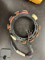
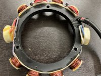
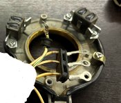
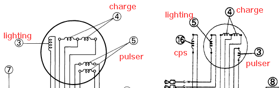
Stator- good - Brown - 208 volts , red - 115 volts , blue-115 volts. When I saw this I realized that the stator did not have a balanced power output per leg.

trigger good. Output from CDI to #1 cylinder was low. This was suspected all along but followed the brown wire when I would roll cyl 1 and cyl 3 in the CDI input. This was the issue where problem seemed to follow the brown wire on the stator. I would move it from #1 stator input to #3 input on the CDI and the problem would follow and reflect on the output of the CDI to coil. This led to my initial though that the stator voltage was out of phase, low or impaired and not fully charging the caps in the CDI.

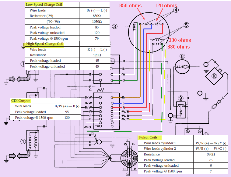
Upon testing the stator with the DVA the brown leg was ~208 volts , blue was ~115 volts and red was ~115 volts . I summise that what was happening was that within the CDI the brown stator input and associated capacitor for #1 cylinder was rated to covert the full three phase 208 voltage to the output required for the #1 coil.

The blue and red stator leads and their respective positions on the CDI were built to convert ~115 volts down to the charge voltage for their respective coil outputs. When I was switching the stator input paths on the CDI around ,I was introducing 208 volts to caps in the CDI that were meant to convert 115 volt input. This is why I believe it appeared to follow the brown stator wire when in fact the other caps may not have been able to handle that voltage.

It does not square why when I put a 115 volt input ( blue wire) into the #1 stator input on the CDI the cylinder meant for 208 volts that it would fire. However, I swapped the CDI with one from CDI electronics and my problem is solved. I now also have a spare stator, and trigger assembly. These are my assumptions with obvious gaps.Can anyone lend any additional logic to this situation?

Thanks-
Havana
 

99yam40

Fleet Admiral
Joined
Sep 7, 2008
Messages
8,891
Boscoe posted good info on how it all works.
what you call the stater is the low speed and high speed charge coils.
were you testing them at different RPM to see if they made spec in manual?
you need to post what the specs are along with what you are reading, even for the pulser coils.
It is very hard to understand without all the proper info

And Boscoe mentioned a couple of times that if all the voltages in to the CDI were good, and the voltages out were not, then the CDI was a prime suspect.
did you even test the out puts?
 
Last edited:

boscoe99

Lieutenant Commander
Joined
Aug 22, 2013
Messages
1,826
Boscoe posted good info on how it all works.
what you call the stater is the low speed and high speed charge coils.
were you testing them at different RPM to see if they made spec in manual?
you need to post what the specs are along with what you are reading, even for the pulser coils.
It is very hard to understand without all the proper info

And Boscoe mentioned a couple of times that if all the voltages in to the CDI were good, and the voltages out were not, then the CDI was a prime suspect.
did you even test the out puts?
Can you explain to me please what this "rolling" stuff is all about?
 

Havana

Cadet
Joined
Feb 12, 2023
Messages
7
Can you explain to me please what this "rolling" stuff is all about?
It's quite simple. you have three phases from the coil that charge three CDI position, you can switch them around if you keep the phase sequence the same. The CDI doesnt care where it gets power. Some CDIs calculate phase angle from other inputs to the CDI, that is why I kept the sequence the same but switched the wires around. This proved my point. Where is the confusion?
 

99yam40

Fleet Admiral
Joined
Sep 7, 2008
Messages
8,891
not sure where you are getting the 3 phases from,
there are 2 charge coils. one for slow speed of the motor( starting and low RPM, and then the high speed coil for higher RPM.
Not even sure how many caps there are in the CDI for that motor.
have you seen something to show this info?

I was thinking that with only 2 pulser coils being able to time the spark for 3 spark plugs,
and with only one slow speed coil to charge the cap during start up.
only one cap is needed to spark all 3 plugs also.
 
Top