Hello,
I have a tricky problem
1992 Yaaha C85 model c85tlrq
Issue : no fire top cylinder
troubleshooting
replace trigger coil - same problem
replace stator - same problem
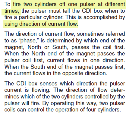
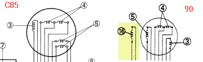
This is one of the 3 cyl C85s where there are only two trigger coils. Per the manual two cylinders #1 and 3 are on the same trigger coil and the CDI recognizes the North South direction of the flywheel magnets to determine whether #1 or #3 should fire.
Inter sting observation. When I roll the trigger inputs #1 to #3 on the CDI. No change
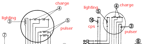
When I roll the stator inputs to the CDI from Brown(#1) Red (#2) Blue (#3) to Blue Red Brown the problem moves to the # 3 cylinder. This is why I replaced the stator. Magnets on the flywheel are in the correct orientation, I verified with a magnet that they alternate around the flywheel and are in the correct orientationl.
I would appreciate any direction.
-Havana
I have a tricky problem
1992 Yaaha C85 model c85tlrq
Issue : no fire top cylinder
troubleshooting
replace trigger coil - same problem
replace stator - same problem
This is one of the 3 cyl C85s where there are only two trigger coils. Per the manual two cylinders #1 and 3 are on the same trigger coil and the CDI recognizes the North South direction of the flywheel magnets to determine whether #1 or #3 should fire.
Inter sting observation. When I roll the trigger inputs #1 to #3 on the CDI. No change
When I roll the stator inputs to the CDI from Brown(#1) Red (#2) Blue (#3) to Blue Red Brown the problem moves to the # 3 cylinder. This is why I replaced the stator. Magnets on the flywheel are in the correct orientation, I verified with a magnet that they alternate around the flywheel and are in the correct orientationl.
I would appreciate any direction.
-Havana