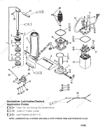
TILT & TRIM PUMP MANIFOLD

mav6759

Chief Petty Officer
Joined
Jun 25, 2007
Messages
489
I have a 1996 Force 90hp that I was having a few issues with the tilt & trim. I decided the to take the tilt & trim motor and pump/manifold apart, I got everything back together except for the pump/manifold. I was wondering if anyone would have the diagram of putting the tilt & trim pump/manifold back together. I have design one with the model number 0E182480 any help would be much appreciated.

Thanks Mav
 

mav6759

Chief Petty Officer
Joined
Jun 25, 2007
Messages
489
No Title

Thanks for the response, I have looked at those picture before. But on the bottom of the tilt trim motor there is a sliver cap (I just found out that the silver cap is the oil pump)..that have 4 bolts. I took the silver cap off the oil pump and everything fell apart. I'm going to try to post some picture of the cap (oil pump), I tried to put it back together. But for the life of me I can't find any diagram of this silver cap (oil pump) and it components. Not even the service manual show anything about the oil pump and it components
 

Attachments

  • photo239413.jpg
    photo239413.jpg
    217.5 KB · Views: 7
  • photo239414.jpg
    photo239414.jpg
    228.4 KB · Views: 8
Last edited:

mav6759

Chief Petty Officer
Joined
Jun 25, 2007
Messages
489
Ok, Since I found no information on the oil pump and buying the service manual, talking to Mercury customer service for the last 4 days and 5 different marine mechanic's, I came up with nothing. I can't believe nobody knows how to put a oil pump back together, 6 little items, So I attempted to put the oil pump back together myself. The tilt and trim is still not working. The motor runs in both directions, but its not lifting the cylinder. The motor is getting very hot to the touch. The one thing that I did notice, is the when I turn the release valve the cylinder is very hard to lift, and when I do lift the cylinder, its like it has a spring pulling it back down. Does anyone know why the motor would be getting as hot as it is, and why the cylinder has so much force against me pulling on it.

Any help would be great,

Thanks Mav
 

pnwboat

Rear Admiral
Joined
Oct 8, 2007
Messages
4,251
I feel your pain. Unfortunately, I've never messed with that style of pump so I can't help. Based on your description, it sounds like you have some parts that are in the wrong place. The pump should have some check valves that will allow the fluid to flow in one direction. On the older pumps, the check valve is a ball bearing with a spring. It almost sounds like your tilt/trim is operating the opposite from what it's supposed to do. Maybe you have a check ball(s) installed backwards? That is the spring is supposed to be on the opposite side of the ball bearing? If you post some pictures of the dis-assembled pump and how you re-assembled it, there may be a chance that someone might be able to take a swag at the re-assembly.
 

mav6759

Chief Petty Officer
Joined
Jun 25, 2007
Messages
489
Thanks, I will break it down in the morning..But one question..When I release the release valve it should allow the cylinder to rise easy.. but this is not the case.The cylinder does move, but it take two people to get the cylinder to move...and when it does move, it lowers right down...however, with other motors I can release the release valve and raise the motor without to much effort. Is this a cylinder issue..because when i try to raise the cylinder by hand it seems I have force pulling against me...

thanks
Mav
 
Last edited:

pnwboat

Rear Admiral
Joined
Oct 8, 2007
Messages
4,251
I would guess that it's probably not a cylinder issue, but don't hold me to that. The cylinders typically have some "O" ring seals to allow them to hold pressure. If the seals goes bad, then it will not hold pressure and you can move the cylinder rod in and out (or up and down). Depends on how bad the "O" ring seal is leaking as to how much effort it takes. Since you have pressure/resistance going up, and much less resistance going down, it sounds more like the there is a check valve installed backwards, or a component of the check valve improperly installed.

Just wanted to clarify, what kind of issues with the tilt/trim were you having before you took it apart?

Here is some comments I found with someone else that has encountered the same problem after taking the pump apart. Note, this is a Mercury design tilt/trim pump that you have on your Force motor. You may find more info on the Mercury Forum.
I was wondering if anybody had a drawing on the tilt trim pump motor? it is a 1995 90hp mercury i thought if i take it apart i could see the problem but who knew there would be springs and ball bearings everywhere. I figured where everything goes back, but one spring. There was a total of 3 springs 2 of them goes on the 2 ball bearings the other 1 ????????

Assumming a 3wire motor (aka black filler plug) - the third spring goes into the hole with the oring recess cut into it. first the spring, then the red ball bearing, then a new oring. There's a lot more to it than a volunteer text based forum will ever touch ... but that should get it working well enough to finish season.
 
Last edited:

mav6759

Chief Petty Officer
Joined
Jun 25, 2007
Messages
489
No Title

I took the pump apart and here is how I put it back together...if I missed something please let me know..The 2 ball bearings, i put into 2 round hole in the cap, hope it is correct. I placed remarks after each picture.
 

Attachments

  • photo239826.jpg
    photo239826.jpg
    290.7 KB · Views: 12
  • photo239827.jpg
    photo239827.jpg
    298.9 KB · Views: 13
  • photo239828.jpg
    photo239828.jpg
    297.6 KB · Views: 13
  • photo239829.jpg
    photo239829.jpg
    316 KB · Views: 11
  • photo239830.jpg
    photo239830.jpg
    298.7 KB · Views: 12
  • photo239831.jpg
    photo239831.jpg
    295.1 KB · Views: 14
  • photo239832.jpg
    photo239832.jpg
    295.8 KB · Views: 14
  • photo239833.jpg
    photo239833.jpg
    364.1 KB · Views: 12
  • photo239834.jpg
    photo239834.jpg
    384.1 KB · Views: 13
  • photo239837.jpg
    photo239837.jpg
    154.9 KB · Views: 13
  • photo239838.jpg
    photo239838.jpg
    347.1 KB · Views: 15
Last edited:

pnwboat

Rear Admiral
Joined
Oct 8, 2007
Messages
4,251
Based on the comments that I found and posted above, it looks like the spring that is in the bolt hole right next to the hole with the "O" ring should actually be in the hole with the "O" ring with one of the ball bearings inserted on top of the spring. Not sure which ball bearing though. Then the "O" ring gets installed on top of the ball bearing. Have to do some trial and error swapping of ball bearings.

Looks like this is a pretty simple set up. From what I can gather, you have the rocker style pump. Very sensitive to contamination. Also a common problem is the the tip of the nylon pressure relief valve breaks off inside the manifold and gets stuck.
 

mav6759

Chief Petty Officer
Joined
Jun 25, 2007
Messages
489
Thank's for the reply, it is possible that there were 3 ball bearings in this unit and I may have lost one...The reason I ask is because under the cap it looks like there is 2 spaces for 2 ball bearings.

Thanks
Mav
 

pnwboat

Rear Admiral
Joined
Oct 8, 2007
Messages
4,251
It might be possible that one is missing, but don't assume that what looks like an obvious spot for a ball bearing means that one should actually go there. That kind of threw me off course when I first attempted to re-build the older style pump.

It looks like your pump is pretty basic as far as the balls and springs. Just a matter of getting them in the right spot. I would try doing what I posted about putting the ball on the spring then the "O" ring unless you see something obvious that doesn't make sense. Also just wanted to mention that just because you see info on the internet doesn't make it correct. In this case though, what do you have to loose. Hopefully you have all the parts and nothing is missing. Just going to take some time and patience.
 

CPHER2003

Recruit
Joined
Jun 25, 2010
Messages
1
Based on the comments that I found and posted above, it looks like the spring that is in the bolt hole right next to the hole with the "O" ring should actually be in the hole with the "O" ring with one of the ball bearings inserted on top of the spring. Not sure which ball bearing though. Then the "O" ring gets installed on top of the ball bearing. Have to do some trial and error swapping of ball bearings.

Looks like this is a pretty simple set up. From what I can gather, you have the rocker style pump. Very sensitive to contamination. Also a common problem is the the tip of the nylon pressure relief valve breaks off inside the manifold and gets stuck.
Hello, I know this is an old post, hoping you can help with the same issue pertaining to the plastic tip broken off in the pump housing.
1996 force 120, (120ELPT, SER#OE171968) it has the early series 1 trim system(eaton?) that has a separate pump (Mercury#811670 7).
couldn't really get the trim to do anything, finally git the valve opened, and was able to lift the motor up, but not all the way up to use the travel locks.
had a buddy that is an o/b tech and we fiddled with the manual valve and the fluid, and was able to get some fluid to where it would start to go down but never up. i pulled the trim assy and then is when i realized that the tip was broken off. got the o ring out , but dont want to scratch the bore.
Is there a good way to remove the tip without damaging the bore?
Thanks!
Chris
 

DaninMCI

Recruit
Joined
Aug 15, 2022
Messages
2
This is an old forum post but this issue still happens where the plastic valve release screw tip breaks off. Hard to believe that this is an issue. You can get aftermarket stainless steel replacement valve release screws from places like amazon but I tracked down the svc bulletin (attached) on this issue on how to remove the tip. Unfortunately the seals and such are not cheap to replace if you tear it down. This is for the 3-wire black plug version but I have to assume the newer version is somewhat the same process although the plastic release valve was improved at some point as well. You can also buy a kit to convert from 3 wires to 2 wires if replacing the motor and going through that. Here is also a parts diagram. 1660560037290.png
1660560080918.png
 

Attachments

  • Tilt trim manifold stuck tip svc bulletin.pdf
    34.5 KB · Views: 5

DaninMCI

Recruit
Joined
Aug 15, 2022
Messages
2
That pump is a Mercury pump. Maybe go to the merc. site and ask there???
Good point but the 18-6777 motor and related parts are mostly the same on Mercury, Mercury Mariner and Force motors in the mid-1990's so it's the same setup basically. I was trying to be helpful and see if someone had some ideas on how to fix this common issue with these pre-yellow cap 3 wire tilt systems.
 
Top