DavidLewis
Cadet
- Joined
- Jan 27, 2016
- Messages
- 17
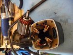
Hi all. My 3-wire tilt/trim motor from a 1979 Mercury 70hp doesn't work. It doesn't rotate when I connect either the green or the blue wire to +12V while the black wire is connected to battery ground. I've dismantled the motor, done all the first-stage checks (looking for continuity / shorts between the various windings and metalwork on armature and stator) and as far as I can tell, it all checks out OK. (I don't have a growler though.)

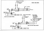
Looking at the internal wiring of the motor, I'm wondering whether a previous owner has attempted an incorrect repair. If I describe what I can see, can anyone tell me whether it's supposed to be internally wired like this please?
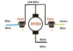
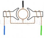
It's a three-wire motor. The green wire is attached to one end of the first field winding. The other end of that field winding has a link wire, which runs to the second field winding on the opposite side of the casing. The other end of the second field winding has a blue wire attached. One of the brushes is connected to the link wire that joins the first and second field windings. The other brush is connected to the motor end plate, which has a black wire bolted to it. I've drawn a diagram:

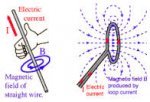
It means that only one of the field windings (on only one side of the motor!) will be energised when, say, the blue and black wires are connected to the battery. This doesn't seem very likely to me - there surely won't be much of a magnetic field across the armature in this case? Is that the way it's supposed to be?
Thanks for your help,
David
Looking at the internal wiring of the motor, I'm wondering whether a previous owner has attempted an incorrect repair. If I describe what I can see, can anyone tell me whether it's supposed to be internally wired like this please?
It's a three-wire motor. The green wire is attached to one end of the first field winding. The other end of that field winding has a link wire, which runs to the second field winding on the opposite side of the casing. The other end of the second field winding has a blue wire attached. One of the brushes is connected to the link wire that joins the first and second field windings. The other brush is connected to the motor end plate, which has a black wire bolted to it. I've drawn a diagram:
It means that only one of the field windings (on only one side of the motor!) will be energised when, say, the blue and black wires are connected to the battery. This doesn't seem very likely to me - there surely won't be much of a magnetic field across the armature in this case? Is that the way it's supposed to be?
Thanks for your help,
David


