sam am I
Commander
- Joined
- Jun 26, 2013
- Messages
- 2,169
Grasshopper,
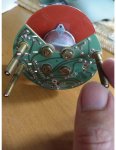
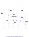
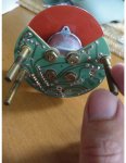
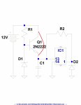
Refer to included pic and drawing below (incomplete BUT most likely enough) ....
By Inspection and your measurements/statement, Q1 (MPS2222) smoked! If this transistor ("xster" for short) opens from emitter to collector (the xster blows up in such a way and doesn't function properly), your tach will never come on, e.g., it's dead because it's not getting power on pin 13.......Q1 job is to turn on pin 13.
How does it do that? I'm glad you asked......
Evil zener diode(EZD) D1 (18V?) and its evil counter part R1 (xx Ohms) sets up a base voltage on Q1 provided by the +12V coming in from your boat. Q1 is configured as a "emitter follower". Sooooo, the voltage the emitter will follow the base voltage less 0.5V.
Ve = Vb - 0.5V (eq. 1)
EZD "clamps" the voltage on the base to 18V or less and its evil partner R1 limits the current. This in-turn protects IC1 from seeing too high of voltage on its pin 13 in the event your boat 12V get crazy high somehow(more on that later).
Why did this xster blow up? I'm glad you asked........
The current path that would blow it up is into the emitter out the collector and to the battery (electron flow for the techies, more on that later) ......If C1 and IC1(and its external components), either of those items short or goes near ground, that xster will get hot and/or pop(explode).......
Why is the copper trace burn't? I'm glad you asked........
That current path to heat that trace up is from ground through EZD D1 and into the base and out collector of Q1 and/or in to and out of R1 back to the battery (electron flow for the techies), the ONLY way that burn't is ...
1) The 12V went waaaaaay up past 18V and R1 was the only thing limiting the current.
2) The 12V went up past 18V and Q1 shorted b to c. (R1 won't be able limit ANY current with a short in parallel)
3) EZD shorted or went down in value, say to 5V or something. (recall I/we never trust them, my gut says we'll be back here)
Next?
Replace the xster, AND add a temp inline 1 amp fuse into the 12V feed BEFORE you apply power to test this thing.
Once the temp fuse is inline, apply power and ground to the tach and if the fuse stays good, test pin 13 of IC1 for around *11.3V. If all is well, hook up the sig and test.
If the fuse blows, IC1 and/or EZD are probably close to if not shorted, we'll address this if need be.
* See equation 1.


Last edited:


