Tachometer repair?

esanford

Cadet
Joined
Jun 28, 2005
Messages
14
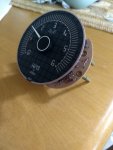
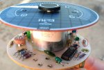
1987 FourWinns 3.0 Mercruiser. My tach stopped working. It doesn't move at all when I turn on the key, or start the engine. I get 12V measured between the purple and black wires, and the gray wire pulses when the engine is running (as measured by my "touch it and get electrocuted" meter :) After opening it up, I cleaned the contacts on the 4-way metal switch and tried it in all positions, and exercised the potentiometer, no effect. I also sprayed electrical contact cleaner down the hole the needle comes out of and exercised the needle.

I've tried looking up parts based on the numbers shown on the board and the "can" for the needle movement with no luck. I don't see any obviousl burnt or otherwise damaged components. I'm no electronic expert, but could I replace all the capacitors like I did on my old stereo to get it working? I could just get a new tach, but I'd just as soon not lose the matching (super 80s) gauge face and needle unless I had to. Does anyone make new tach internals I could put behind them? Any other ideas?

Thanks!
 

Scott Danforth

Grumpy Vintage Moderator still playing with boats
Staff member
Joined
Jul 23, 2011
Messages
49,534
there are companies that can repair your tachometer. these are like the Speedometer Service shop in Milwaukee WI, or D&D Speedometer in the twin cities. however for the cost of getting your old tach repaired, you can get most of a new gauge package.
 

Chris1956

Supreme Mariner
Joined
Mar 25, 2004
Messages
27,837
Normally to repair, you remove the gauge, and give it a "float" test. If it floats in the water, it is good. If not, you buy a new one.
 

Scott Danforth

Grumpy Vintage Moderator still playing with boats
Staff member
Joined
Jul 23, 2011
Messages
49,534
:laugh::laugh::laugh::laugh::laugh::laugh::facepalm:
 

GA_Boater

Honorary Moderator Emeritus
Joined
May 24, 2011
Messages
49,038
Normally to repair, you remove the gauge, and give it a "float" test. If it floats in the water, it is good. If not, you buy a new one.

This is a proven diagnostic troubleshooting step. :lol:
 

gm280

Supreme Mariner
Joined
Jun 26, 2011
Messages
14,604
"IF" you honestly knew anything about electronics, I'd say YES. However, not knowing or understand how a tach works would only confuse you at trying to find the defective part or parts. Can it be fixed? Absolutely! Can you fix it? Maybe and maybe not. They really are not that complicated to fix but you really have to know and understand what they really are to be able to fix it without destroying it beyond fixable... JMHO
 

esanford

Cadet
Joined
Jun 28, 2005
Messages
14
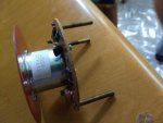
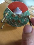
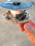
sam am I The needle DOES move significantly (~60 deg) when I use a multimeter with diode check across the various points on the movement (sometimes up, sometimes down). I suppose this just tells me the problem is in the circuit board, right? (I've attached pictures below.)

gm280 I've been troubleshooting my whole life for a living (electro-mechanical systems and computers) but don't have much experience with electronics, but I'm very interested to learn and have been doing some beginner reading lately. Anything you could give me to point me in the right direction on this? Destroying it beyond fixable wouldn't put me in any worse spot than I am now :joyous:

Scott Danforth thank you, I emailed D&D, but I suspect you're right.
 

Attachments

  • IMG_20200814_091507814.jpg
    IMG_20200814_091507814.jpg
    557.8 KB · Views: 3
  • IMG_20200814_091519231.jpg
    IMG_20200814_091519231.jpg
    464 KB · Views: 3
  • IMG_20200814_091543677.jpg
    IMG_20200814_091543677.jpg
    625.1 KB · Views: 3
  • IMG_20200817_090905401.jpg
    IMG_20200817_090905401.jpg
    481.4 KB · Views: 3

sam am I

Commander
Joined
Jun 26, 2013
Messages
2,169
sam am I The needle DOES move significantly (~60 deg) when I use a multimeter with diode check across the various points on the movement (sometimes up, sometimes down). I suppose this just tells me the problem is in the circuit board, right? (I've attached pictures below.)

OMG, real clear decent pictures.!!!........THANK YOU JESUS!!!

Yes, (and this is a good thing) and are you 100% on a good signal source? That thing should work, unless. the driver IC is bad...usually not though.

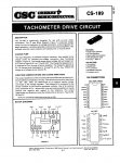
https://www.onsemi.com/pub/Collateral/CS8190-D.PDF


So, a few other things to check......

Check the ALL the PN junctions (0.5V-0.7V) on the red circled things with your meter's diode check and make sure the IC is getting it's Vcc (Pin 8) and ground when 12V/Gnd are applied to the studs.


Click image for larger version  Name:	image_337910_a.JPG Views:	1 Size:	222.5 KB ID:	10918256
 
Last edited:

gm280

Supreme Mariner
Joined
Jun 26, 2011
Messages
14,604
Okay unless the meter movement itself is open, this IS fixable. Follow "sam am I's" suggestions and if those parts check out, then it is either the DIP chip or the meter movement. However, that is only IF you are getting a signal from the engine.

Also when using your "Diode" function on the meter, if you don't get a reading, swap the leads around and check again. On the blue three legged part, use the center to check the other two leads. And again if no reading, swap the leads around and check again.

Post your results.
 

sam am I

Commander
Joined
Jun 26, 2013
Messages
2,169
Okay unless the meter movement itself is open

Had him check that, he's confirmed it's good by the test i had him do...See below

sam am I The needle DOES move significantly (~60 deg) when I use a multimeter with diode check across the various points on the movement (sometimes up, sometimes down)


and the gray wire pulses when the engine is running (as measured by my "touch it and get electrocuted" meter :) !

This ^^^ worries me a tad, and is why I'm asking him to re-check it, did it shock you for real?..... Not so sure I understand what you're saying here....Anyone out there know where the signal comes from? The distributor coil perhaps? Yes? Then I reckon getting a lil bite could happen as there is a flyback voltage (90'ish volts P2P) off the coil when the points open, this makes sense then if he did. BUT, working as hard as they do/can, a front end component might have open (or shorted) and took down the input signal to the driver IC.

At any rate, we'll get there, the movement being good is a definite plus for him, the rest is easy pesy.

Man I soooooo love being cheap!!!
 
Last edited:

gm280

Supreme Mariner
Joined
Jun 26, 2011
Messages
14,604
Next question I ask, was this tach working in it's present setup (no wires changed or anything else) at once and then just quit? And if so, have you changed anything with any wires or circuit on the boat before noticing this?
 

sam am I

Commander
Joined
Jun 26, 2013
Messages
2,169
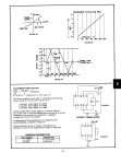
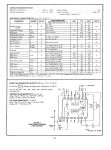
Apologies and correction to the above INCORRECT data sheet..........geeesh, it was too early.

Click image for larger version  Name:	Scans-0042073_Page_1.jpg Views:	1 Size:	547.7 KB ID:	10918425

If we're convinced the signal input to the tach and wiring were all good and........

Vcc/B+ is pin 13........NOT pin 8 as I indicated above in post #11. Also check "Vreg" (pin 11) for approx 8.5V.

If after you power it up to check pin 13 for 12V and IF it's NOT there, check that zener diode (18V) and limiting resistor (15 ohms) as seen on page 2 of the data sheet that's hanging (wired) off the IC's pin 13..........I believe (as far as i can see from your pictures) the tach manu followed the IC's manu's recommendation and added it. It serves as a voltage clamp to prevent over voltage on the IC from the external voltage source (your boat).

Zener's are evil diodes as they are always working in reverse avalanche mode, never trust them!!! I don't...
 

Attachments

  • Scans-0042073_Page_2.jpg
    Scans-0042073_Page_2.jpg
    512 KB · Views: 3
  • Scans-0042073_Page_1.jpg
    Scans-0042073_Page_1.jpg
    547.7 KB · Views: 3
Last edited:

esanford

Cadet
Joined
Jun 28, 2005
Messages
14
Thank you for all the great help here guys. Yes, the tach is the original to the boat and just quit one day last summer. In checking the diodes I discovered that the transistor (toward the back of the pic) actually has a chunk missing, and one of the traces on the back of the board looks like it got hot and melted the coating above it- there is still continuity across it however. I have a new MPS2222 (actually MPS2222A, I couldn't find the other) on the way. The existing one reads ~0 in both directions across one of the leg pairs.

Touching the signal wire with the engine running feels like touching a spark plug, but way less painful. It's definitely pulsing with the RPMs. I think it does come off the coil, but I haven't verified this.
 

gm280

Supreme Mariner
Joined
Jun 26, 2011
Messages
14,604
Sounds like you found your damaged part providing the one leg isn't parallel with another part throwing the reading off. I am assuming the transistor is a 2N2222 type since you ordered a MPS2222 as a replacement. Just verify the pin outs are the same between the two and replace it and you should be taching again.
 

sam am I

Commander
Joined
Jun 26, 2013
Messages
2,169
Cool Beans!!

Touching the signal wire with the engine running feels like touching a spark plug, but way less painful. It's definitely pulsing with the RPMs. I think it does come off the coil, but I haven't verified this.

The pulsing is a good sign HOWEVER this doesn't concern me so much as the amplitude of said signal and the exploded parts........Could be normal as stated, flyback voltage off the coil will be a tingle.

Tread cautiously Grasshopper and always remember and never forget!!

"One who questions his (her) findings, will never have to buy additional parts and finds his (her) straightest path to ones own inner cheapest bastard (b*tch)"

....Me
 
Last edited:

gm280

Supreme Mariner
Joined
Jun 26, 2011
Messages
14,604
The reason I suggested he makes sure the pin outs are the same is because a 2N2222A is not the same as a P2N2222A. They reversed the leads. So make certain what you get before installing it...
 

esanford

Cadet
Joined
Jun 28, 2005
Messages
14
The transistor has MPS2222 (and the Motorola logo) printed on the side, and the datasheet covers both MPS2222 and MPS2222A, with "* Motorola Preferred Device" indicated next to the A version. Places that sell them seem to use the numbers interchangeably. LINK

Should I be checking anything else before replacing that so I don't end up just blowing up another transistor?
 
Top