tach voltage?readings

donke

Recruit
Thread starter
Joined
Dec 24, 2013
Messages
4
I have a 1988 Evinrude 100 V4. First time out this year the tach stopped indicating RPM. Tach worked fine last year. I cleaned the terminals on the tach indicator to no avail. I measured DC voltage at the indicator from the common to the pul post. At idle I get approx +30 mv. When I increase throttle while in neutral the dc voltage goes progressively more negative beween -30 to -60mv according to more throttle. My question is does anyone know if my voltage behavior at the tach indicator is normal? Thanks.
 

flyingscott

Fleet Admiral
Joined
Apr 8, 2014
Messages
8,348
tachs usually fail for 2 reasons tach goes bad or a bad rectifier. You need to check the rectifier as your tach gets it's signal from that.
 

F_R

Honorary Supreme Mariner
Joined
Jul 7, 2006
Messages
28,226
In the first place it is receiving pulses, not pure dc. I'd have to think about it, maybe 1/2 wave AC?? Never mind, it is an invalid test. As said, first thing to check is your rectifier.
 

boobie

Supreme Mariner
Joined
Nov 5, 2009
Messages
20,826
I think you should get 8 -9 .6 volts on a peak reading volt meter on the gray wire.
 

donke

Recruit
Thread starter
Joined
Dec 24, 2013
Messages
4
No Title

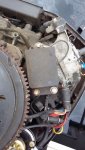
I'm doing a resistance check on the rectifier. Is the rectangular black box in the pic the rectifier? I don't see anything that looks like a small round cylinder canister like I have seen on the web. Using the ohms, diode setting on my multimeter I get 1.1 from the rectifier pin in the plug shown to ground and .5 reversed. the other pin I get the same but in reversed. Is the rectifier bad per readings? Thanks.
 

Attachments

  • photo243336.jpg
    photo243336.jpg
    223.9 KB · Views: 0

Fed

Commander
Joined
Apr 1, 2010
Messages
2,457
Your rectifier/regulator will probably be under the flywheel and to test is somewhat difficult. Need ammeter & variable resistance to test at 4-5K RPM.

What most do is test the stator resistance & also test stator for ground faults.
Then test the battery standing voltage and compare with the battery voltage when the motor is running.

So, disconnect the stator wires at the terminal block and test continuity resistance & test for ground faults.
Yours should probably be a 9 Amp stator which should have a resistance of 0.7 Ohms and NO continuity to ground.

Then test the battery voltages both standing & running.
 

Vic.S

Rear Admiral
Joined
May 4, 2004
Messages
4,721
I'm doing a resistance check on the rectifier. Is the rectangular black box in the pic the rectifier? I don't see anything that looks like a small round cylinder canister like I have seen on the web. Using the ohms, diode setting on my multimeter I get 1.1 from the rectifier pin in the plug shown to ground and .5 reversed. the other pin I get the same but in reversed. Is the rectifier bad per readings? Thanks.
No isn't that the power pack ?
If you dont have the round 3 wire type of rectifier I guess you must have a (watercooled ) rectifier regulator mounted in the top of the engine block. Isn't it it what is just peeping out from under the flywheel , one corner at about 1 o'clock.

should You will find some useful info in the CDI Electronics Troubleshooting Guide. https://issuu.com/cdielectronics/doc...ition_troubles
 
Last edited:

F_R

Honorary Supreme Mariner
Joined
Jul 7, 2006
Messages
28,226
Motor has a combination regulator / rectifier. Center rear, on top of block, under the edge of the flywheel.
 

SparkieBoat

Captain
Joined
Aug 17, 2009
Messages
3,643
try CDI electronics troubleshooting guide. It is free. You will need a DVA adpater ($30) and a good multimeter. Boobie is correct you should have over 8 V DVA on the gray wire while running, easy test to do. also check the voltage on both yellow wires to ground. they should be over 20 I think.
 

SparkieBoat

Captain
Joined
Aug 17, 2009
Messages
3,643
I have replaced more regulators than anything on those omc V-4s and V-6s. they just do not last for some reason.
 
Top