Stator Rewrap

gm280

Supreme Mariner
Joined
Jun 26, 2011
Messages
14,602
How about a cordless drill? It can be controlled for speed and not so fast as to get out of hand. :noidea:
 

Pusher

Lieutenant
Joined
Sep 2, 2014
Messages
1,273
Thanks for the thoughts from both of you. I actually used a cordless drill on the first two wraps when I wound onto the spool for the bobbin. It worked well for that.

I also have the sewing machine motor already because I do my own rods too and thought I better get the setup for curing before my brother refused to do it for me anymore :) so I think I'm set on that part. I'll make up my dumby coil armature this weekend and get your thoughts on it to make sure I'm not wasting more time if that's okay. Everything's purchased for the dumby and at this point I'm doing it because I don't like giving up with the idea of success so close.

I noticed that you said the resistancewas for transformers. I have both of the original low speed and high speed coils and the low speed is about half the wraps of the high speed. I was thinking I would wrap to match the ohms listed in the seloc manual. Am I barking up the wrong tree?

On another note, winter is flying by with this project to entertain me!
 

gm280

Supreme Mariner
Joined
Jun 26, 2011
Messages
14,602
Thanks for the thoughts from both of you. I actually used a cordless drill on the first two wraps when I wound onto the spool for the bobbin. It worked well for that.

I also have the sewing machine motor already because I do my own rods too and thought I better get the setup for curing before my brother refused to do it for me anymore :) so I think I'm set on that part. I'll make up my dumby coil armature this weekend and get your thoughts on it to make sure I'm not wasting more time if that's okay. Everything's purchased for the dumby and at this point I'm doing it because I don't like giving up with the idea of success so close.

I noticed that you said the resistancewas for transformers. I have both of the original low speed and high speed coils and the low speed is about half the wraps of the high speed. I was thinking I would wrap to match the ohms listed in the seloc manual. Am I barking up the wrong tree?

On another note, winter is flying by with this project to entertain me!

You can wrap to the resistance listed in the Selco manual "IF" you know for sure you are using the exact same gauge wire. Otherwise, it is still only a guess on the info and number of wraps. I am looking at this via technical ideas and mindset. Math doesn't lie. JMHO
 

StarTed

Senior Chief Petty Officer
Joined
Jul 14, 2015
Messages
694
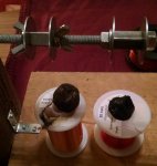
I think your idea of using a variable speed drill is a good one. You could use some threaded rod and several nuts to secure the spool to the threaded rod. That way you can chuck the rod in the drill and attach a counter to the other end. The inside of an old speedometer cable should work fine if you can make some couplers to attach it.

I'd count the turns for the first one that is wound with the proper amount of magnet wire. A wire gauge should tell you what diameter the old wire is so you can duplicate it exactly. I use a wire gauge to select the proper wire diameter when I wind a transformer. There is also a formula for determining the power output from the cross section of the laminated core if you know the metal's properties. I have that somewhere but I don't know where now. My move 10 years ago left me with some things still unpacked and undiscovered. :)

Maybe you could wrap up a sample coil and measure the resistance of the wire. Then unwind 10 turns and remeasure the resistance removing the unwound wire. If you can't tell the difference between a turn I'd use a counter.

Good Luck.
 

Pusher

Lieutenant
Joined
Sep 2, 2014
Messages
1,273
image_255028.jpg image_255029.jpg

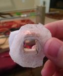
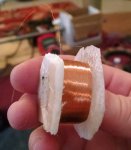
Behold my hideous creation. Tonight I'll put the epoxy base into the forms. With any luck, I'll be spinning them up tomorrow morning.


Good thoughts again guys.

Upon further inspection I've concluded the highspeed coil is very close if not 42 AWG.

The low speed looks to be slightly smaller than my 30 AWG, so probably more like 34-36 AWG. I'll stick with the 30 since I have it. It's hard to tell since the epoxy coating was cooked off the original stuff.

You might be able to see the original gauges from the pics.
 

StarTed

Senior Chief Petty Officer
Joined
Jul 14, 2015
Messages
694
Looks like it might work out for you.

If you use larger gauge wire you'll read less resistance for the same number of turns. You need the same number of turns as originally designed to get the proper voltage regardless of the gauge. The gauge will determine the burden it can handle.

You measure the gauge of a wire with the insulation (varnish) removed being careful not to scrape the wire down in size. Maybe some kind of stripper (paint stripper) could be used if it doesn't attack the wire.

Go for it.
 

Fed

Commander
Joined
Apr 1, 2010
Messages
2,457
Heat the wire up then grip it with a rag and pull it through.
Done it 1000s of times.
 

Pusher

Lieutenant
Joined
Sep 2, 2014
Messages
1,273
image_255075.jpg image_255076.jpg image_255077.jpg image_255078.jpg 6,000 ohms. Soldering this is going to take some steady handwork!!
 

gm280

Supreme Mariner
Joined
Jun 26, 2011
Messages
14,602
That look pretty good. I hope it does what you want it to do this time. :thumb:

Pusher, the secret to soldering anything, is clean wire and flux. If everything is clean and ready to go, a few seconds of heat and a tinny bit of solder will quickly solder anything up. So if you get the insulation off the wire (could even use lacquer thinner or finger nail polish remover to do that), you could even tin the wire. If it tins really easily, you know it is clean and ready to go. Maybe practice on a few pieces of that magnet wire to get the hang of it first. JMHO
 
Last edited:

Pusher

Lieutenant
Joined
Sep 2, 2014
Messages
1,273
Haha, me too. Bolting a running 50hp evinrude would almost be as satisfying.

It's nice knowing I have that option now.

:)
 

Fed

Commander
Joined
Apr 1, 2010
Messages
2,457
6,000 ohms. Soldering this is going to take some steady handwork!!
Back in the day we simply twisted the wires together, cut them off and positioned the cut matching ends vertically.
Heated the cut tips with the oxy to form a little 'ball' of weld on the top, didn't even bother removing varnish from the wires.

You might want to try a couple of tests, twist the wires to form an upside down Y then weld.
I hope that makes sense.
 

Pusher

Lieutenant
Joined
Sep 2, 2014
Messages
1,273
Back in the day we simply twisted the wires together, cut them off and positioned the cut matching ends vertically.
Heated the cut tips with the oxy to form a little 'ball' of weld on the top, didn't even bother removing varnish from the wires.

You might want to try a couple of tests, twist the wires to form an upside down Y then weld.
I hope that makes sense.

That does make sense! I'll give that a try. Good point on doing test runs too guys. Thanks for the feedback.

So would it be best to rubberband and epoxy the main wires around the coils BEFORE I soldier the ends togather? My biggest issue seems to be that the coil wire could easily break off with a little weight and movement.
 

Fed

Commander
Joined
Apr 1, 2010
Messages
2,457
Sure, secure all the leads before you connect them to the winding wire so there can't be any movement at all.
 

Pusher

Lieutenant
Joined
Sep 2, 2014
Messages
1,273
Well, I gave it a test run. Here are the results.

Low Speed:
VDC .9 on setting 20
VAC 280 on setting 200

High speed
VDC 0? on setting 20
VAC 2000 on setting 200

I don't know what that means but it sounds wrong.
 

km1125

Chief Petty Officer
Joined
Aug 10, 2016
Messages
503
I might have missed something from a previous post, but when you say you "gave it a test run", what does that mean?

If you put it on the motor and gave it a spin, simulating a running engine, then you should not get any DC volts. You're creating an alternator, so you should only read AC volts.
 

StarTed

Senior Chief Petty Officer
Joined
Jul 14, 2015
Messages
694
km1125 you make a good point. You should be testing AC voltage while running if testing off the windings.

Did you rerun your tests just to make sure nothing changed during the testing? I'm thinking a possible wiring insulation failure somewhere.

If the readings are too high, too many turns, if too low, not enough, erratic something is not working properly.

By the way, the windings look good.

At least it's a fun project.
 

Pusher

Lieutenant
Joined
Sep 2, 2014
Messages
1,273
Hmm, well if I'm cranking out that kind of AC voltage shouldn't I be getting a reading out of the switch box?

Sorry1125, spun the flywheel but not running. I cranked without the plugs in to be sure it was spinning fast enough.

Is it correct that there's no way to test the switch box without a dva?
 

GA_Boater

Honorary Moderator Emeritus
Joined
May 24, 2011
Messages
49,038
VAC 280 on setting 200

VAC 2000 on setting 200

How are you reading 280VAC and 2000VAC on the 200VAC scale? 200VAC is the max on that scale unless you have an auto-ranging meter.
 

gm280

Supreme Mariner
Joined
Jun 26, 2011
Messages
14,602
Thanks GA. I'll try to confirm this.

Maybe the scale is a multiplier and not a max range setting. Like with resistance scales 1X, 10X, 100X and so on... I have no idea just making a possibility statement.

He could rig up a test with a drill press and the flywheel. He could spin the flywheel attached to the drill press and have the stator underneath so he could see the output voltages. Just an idea.
 
Top