Stator Rewrap

Pusher

Lieutenant
Joined
Sep 2, 2014
Messages
1,273
Also, I thought when I looked the stator up it was supposed to be part number 398-5704A 7. Anyone know the difference between the 4 and 7?
 

gm280

Supreme Mariner
Joined
Jun 26, 2011
Messages
14,600
Don't toast the stator...at least not yet. If you own a Dremel tool take a fine grinding bit and work the plastic off a bit at a time. Once you get to the ends of all the wires you plan to replace, stop grinding. And from the looks of the stranded wires, they look charred. So you will have to clean off any charred insulation to good clean copper wire again. That can be done with either small Exacto knife and patience, or a scrapper of sort. The object is to get to clean copper wire to be able to solder the new leads onto them. You just have to go slow and easy. But it can be done and I have done such things myself before. But it isn't a quick rushed type work. JMHO.
 

Pusher

Lieutenant
Joined
Sep 2, 2014
Messages
1,273
Yeah, I might have to go to Harbor Freight and get a throw away kit.

I feel like a roll of copper would be cheaper but I'll defer to your better judgement and save myself the headache until necessary.
 

Pusher

Lieutenant
Joined
Sep 2, 2014
Messages
1,273
Two quick questions.

1.) Can you only edit a post for a limited amount of time before the "Edit" button disappears when logged in?

2.) Why are you supposed to use the same gauge magnet wire for the wrap job? I know the amps/volts or something increases, but isn't that what the rectifier is supposed to rectify anyway? I would never re-wrap this stator in this gauge, it would take a millennium. All the threads linked in this thread used 20 gauge. Shouldn't that work? I'm no electrician so please enlighten me if you have the time.
 

GA_Boater

Honorary Moderator Emeritus
Joined
May 24, 2011
Messages
49,038
Two quick questions.

1.) Can you only edit a post for a limited amount of time before the "Edit" button disappears when logged in?

2.) Why are you supposed to use the same gauge magnet wire for the wrap job? I know the amps/volts or something increases, but isn't that what the rectifier is supposed to rectify anyway? I would never re-wrap this stator in this gauge, it would take a millennium. All the threads linked in this thread used 20 gauge. Shouldn't that work? I'm no electrician so please enlighten me if you have the time.

EDIT - 1) 5 minutes to make edits without the edit notice and the total edit window is 1 hour. After an hour the Edit button disappears.

2) I think you should give up trying a re-wrap. The wires off the stator are bad and need to be replaced. Dig into where the bell/magnet wires are soldered to the external, clean up the ends and solder the new external wires. Are you sure the wraps are bad?

3) If you do continue with the re-wrap, yes, the wire gauge matters and the number or wraps and the direction of the wraps. Why - Because gauge determines how much current the wire can handle and how many wraps will fit on the core. The direction is all about magnets inducing the correct polarity and a reversed wrap will block current.
 
Last edited:

Pusher

Lieutenant
Joined
Sep 2, 2014
Messages
1,273
Wouldn't the larger gauge increase flow of current though, something an after marjet rectifier or rectifier/regulator could meter?

Is the smaller gauge for maintaining current at idle? I believe the CDI unit for my model is also wrapped in 20 gauge.

Not trying to argue, just explaining where my confusion lies. Thanks GA
 

gm280

Supreme Mariner
Joined
Jun 26, 2011
Messages
14,600
Pusher, if you elect to go larger gauge wire to be able to carry more current, then you have to wrap that same number of turns as well to keep the voltage correct. And that is where the problem comes in. The larger gauge wire takes up a heck of a lot more space and will never allow the same number of windings without getting too large for the stator to fit properly back it its original place on the engine. So you have to stay with the same size and gauge wire if you rewrap. But I don't know why you would rewrap the entire stator. Fix the lead in wires and seal it up again and happy boating. JMHO
 

GA_Boater

Honorary Moderator Emeritus
Joined
May 24, 2011
Messages
49,038
Wouldn't the larger gauge increase flow of current though, something an after marjet rectifier or rectifier/regulator could meter?

Is the smaller gauge for maintaining current at idle? I believe the CDI unit for my model is also wrapped in 20 gauge.

Not trying to argue, just explaining where my confusion lies. Thanks GA

No and no. You might get away with it and you might not.
 

Pusher

Lieutenant
Joined
Sep 2, 2014
Messages
1,273
Ugh, it's so hard to understand what you can't see. I think you're breaking through my thick skull though.

I picked up a dremel today to see if I can seperate things but this plastic they poured in is pulling unintended parts with it. I also grazed the paper protecting the coils. I'm worried the coating was compromised.

I'll know better this afternoon. 3 minutes left in the Seahawks game.
 

GA_Boater

Honorary Moderator Emeritus
Joined
May 24, 2011
Messages
49,038
Time to bite the bullet and find another stator, Pusher.

You can keep practicing.
 

Pusher

Lieutenant
Joined
Sep 2, 2014
Messages
1,273
Thanks GA, but I haven't gotten out on the boat yet and the season's over so I don't have any rush.

I got down to good yellow leads, but I have no resistance between the ground and blue lead now. I might have done that when I marred the coil.

So the question I have is this.

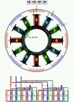
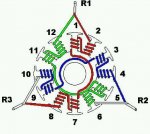
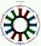
1.) Am I using an Aabbcc or an abcabc pattern?

2.) What are the yellow leads connected to? Would red, blue and yellow each come from one of the splices coming out? I assume the two yellows would be spliced together?

3.) I see there are two setups... one where there is a division between coils and then the other where it all runs together. Would I have the continuous version?
image_253315.jpg
image_253317.jpg
image_253318.jpg
image_253316.jpg
 
Last edited:

Pusher

Lieutenant
Joined
Sep 2, 2014
Messages
1,273
I am kind of stumped. The CDI stator (398-5704A 7) looks like it is wrapped on 12 posts. There are 12 magnets. All of the how-to's say you can't have a 12N12P. Can someone clarify this for me?

I'm also still not sure which of the above wraps is the right one.

Does anyone know?
 

Pusher

Lieutenant
Joined
Sep 2, 2014
Messages
1,273
Does anyone know of a good electrical oriented forum I might get the last of this info from?
 

Pusher

Lieutenant
Joined
Sep 2, 2014
Messages
1,273
Aqui esta una pelicula que es mas grande que todos los otras.

I'll be melting the sucker this weekend and I think after watching this video a couple times I should be good.
 

Pusher

Lieutenant
Joined
Sep 2, 2014
Messages
1,273
If anyone has any better ideas on getting the case off I'm open. The dremel tool wasn't going to cut it (That's kindda punny).
 

GA_Boater

Honorary Moderator Emeritus
Joined
May 24, 2011
Messages
49,038
Hit it with a hammer, it may crack for a starting point.

If you had a stator like the video, you could rewind it. With a potted, encased stator like you have, it's pretty much non-repairable. Getting it open will destroy what you need to know for a rewind, like number of wraps and direction because the coils are embedded in the plastic. You'll see.
 

Pusher

Lieutenant
Joined
Sep 2, 2014
Messages
1,273
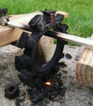
image_253593.jpg I think I am going to be able to piece most of this puzzle back together actually. Fall, a warm campfire... Everything but the marshmallows.
 
Last edited:

Pusher

Lieutenant
Joined
Sep 2, 2014
Messages
1,273
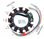
I've noticed that the after market stators seem to have some slight modifications. The one pictured below was wrapped on two extra posts whereas the OEM stator didn't have the 9th & 10th post wrapped. Also, posts 11 and 12 were the ones wrapped in a very fine gauge. I was not able to see which way they were wrapped. The red lead went to one coil and the blue lead went to the other coil. The ground lead I believe joined both coil 11 and 12 which then went to the power head. Please tell me if this seems wrong.
(Don't ask me why this replacement stator has an extra red and blue lead but no black one) :help::noidea:

I am thinking coil 11 & 12 should be wrapped CW and CCW respectively. Please correct me if this is wrong! :dejection:

Tomorrow I plan to run to the local store and get magnet wire, file the corners smooth, maybe borrow a sandblaster if I'm lucky, and then epoxy on some new insulating material on. Any thoughts on a better insulator/encapsulation? I thought gauze, but that might become flammable... as would athletic tape. The problem with Epoxy is it will allow the coils to ground if it overheats enough to melt. I've heard of using JB Weld, but then I couldn't see my coils later on. Hmmm:playball:

To anyone following me; Stator posts 11 & 12 don't have a "foot" to retain the coils, so when your plastic melts, it'll just slip right off with the plastic if melting it upside down like I did. You may want to melt it sideways so it doesn't go anywhere and you can also tug at the red/blue leads to start unwrapping it to see which direction the coils are wound. Just my 02?

If I wind tomorrow, I plan to hook up my ohm meter to the coil wire and the stator body to make sure I'm not grounding as I go.
Whether I take it or not, any and all advice is appreciated!!!

Capture.PNG
 
Top