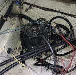
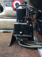
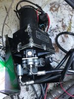
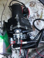
Stand-alone tilt/trim pump

BrianVT

Petty Officer 2nd Class
Joined
Jun 17, 2021
Messages
111
I'm not sure if this pump is specific to Mercury or is generic since it's on board and not on the engine. It runs to a 1980's 70hp Mecury outboard.
The pump motor still runs but I started having no trim/tilt and no reverse lock (related?). There is some clear oil on the floor under the pump. I'm hoping I can just add oil as needed to finish what's left of the Maine, USA boating season and fix it properly after I pull the boat out of the water for the season. There is no oil tank to fill. There is a knurled bolt that seems like it might be where oil would be added? (see arrow in first picture)
Advice on adding oil as needed and also a proper fix, please?
I will get some absorbent pads to contain the oil and keep it out of the bilge and lake.
I found 1 pic online that looks similar to my pump but is a better picture than I could get (attached). Maybe that will help.
 

Attachments

  • Trim pump.jpg
    Trim pump.jpg
    1.4 MB · Views: 20
  • Other pump pic.JPG
    Other pump pic.JPG
    2 MB · Views: 19
Last edited:

Alumarine

Captain
Joined
Feb 22, 2005
Messages
3,735
In the picture of the other pump on the right hand side just below the large red electrical plug is a slotted machine screw.
That's the fill plug.
If clear oil came out of it put 10W-30 motor oil in it.

They're not generic.
They're used in older Mercury outboards and I think all Mercruiser stern drives.
 

BrianVT

Petty Officer 2nd Class
Joined
Jun 17, 2021
Messages
111
Thank you.
Would the low fluid also cause the reverse lock to not be working?
I just noticed the sticker below the fill plug in that picture. Is says to fill to bottom of the threads with the engine tilted up. How to tilt the engine up? Will I be able to tilt it up by hand, and then lock it, with the boat in the water?
 
Last edited:

Chris1956

Supreme Mariner
Joined
Mar 25, 2004
Messages
27,943
Turn the knurled knob full CCW, with the motor down. Now fill the pump reservoir, as Alumarine described. Now see if she will trim up.

On those older motors, with the original PTT control panel, you need to push 2 buttons at the same time for tilt to work.

On the bottom of the PTT pump/reservoir is a control valve. It has 4 orings and a plate, connecting it to the pump/reservoir. The pump often leaks there. The top of the pump/reservoir attached to the base with screws and a gasket. Make sure those are tight, or it will leak there.
 

BrianVT

Petty Officer 2nd Class
Joined
Jun 17, 2021
Messages
111
Thank you.
So...turn full CCW (if it's not already), fill to bottom of threads, replace fill screw, leave knob at full CCW, and try the tilt up button. Correct?
Then check fluid level at full up?
Then leave the knob at full CCW while boating?

I don't know about the 2 buttons you mention. I only know of the up/dn thumb button on the fwd/reverse control.

I did look into the seals. Looks like four 021 o-rings. Not sure which material to get. Buna-N?
 

Chris1956

Supreme Mariner
Joined
Mar 25, 2004
Messages
27,943
yes on all points. The original control panel had a separate trailer button. I guess your trim limit switch was bypassed over the years, allowing the use of 2 buttons. That's fine.

I wouldn't worry about the oring material. They were likely rubber in the 80's and lasted 40 years. The control valve will mold 2 into oblong shapes, for some reason.
 

1960 Starflite

Petty Officer 1st Class
Joined
Jun 23, 2011
Messages
380
Brian, Would you post a picture of cylinder (s) I have a pump system I'd like to modify for my 1975 85hp outboard
 

BrianVT

Petty Officer 2nd Class
Joined
Jun 17, 2021
Messages
111
Brian, Would you post a picture of cylinder (s) I have a pump system I'd like to modify for my 1975 85hp outboard
I assume you mean the lift cylinders on the engine.
My boat is in the water so I'd have to hold my phone out over the water. Not sure I want to do that but I will see what I can do next time I'm down there.
 

BrianVT

Petty Officer 2nd Class
Joined
Jun 17, 2021
Messages
111
On the bottom of the PTT pump/reservoir is a control valve. It has 4 orings and a plate, connecting it to the pump/reservoir. The pump often leaks there. The top of the pump/reservoir attached to the base with screws and a gasket. Make sure those are tight, or it will leak there.
Things have just thawed out here and I'm finally looking at this pump.
I wanted to search for an exploded view but there are no readable markings so I don't know what to search for.
Where should I be digging to get at these Orings?
 

Attachments

  • image0.jpeg
    image0.jpeg
    1.8 MB · Views: 8
Last edited:

Chris1956

Supreme Mariner
Joined
Mar 25, 2004
Messages
27,943
The control valve bolts thru the plate to the reservoir body. Simply remove those bolts and the control valve, with the hoses attached will come off, exposing the plate and it's 4 orings, 2 on each side of the plate.
 

BrianVT

Petty Officer 2nd Class
Joined
Jun 17, 2021
Messages
111
Thanks for the reply.
Do you mean these bolts?
 

Attachments

  • Valve screws.jpeg
    Valve screws.jpeg
    2.6 MB · Views: 13

merc850

Commander
Joined
Jul 7, 2010
Messages
2,046
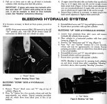
Before you tear it apart here are the bleeding instructions for the rams (some of them have a 3/16" Allen screw) I would do this first:
power-trim-bleedingsmall.jpg
 

Chris1956

Supreme Mariner
Joined
Mar 25, 2004
Messages
27,943
Gee, you are asking a lot for me to ID the bolts from the picture. The bolts are obvious, as they are the only ones visible.
 

BrianVT

Petty Officer 2nd Class
Joined
Jun 17, 2021
Messages
111
So I replaced the four O-rings with Quicksilver part # 25-48171.
Only 1 of the old ones looked bad.
It still leaks. (see video)
What to do now? Or might I have the wrong O-rings? (edit: I rechecked and it looks like correct O-rings)
Also, on the other half of the assembly, the part that the bolts go through, there were grooves that had black in them that looked like they might also be O-rings? They were odd shaped grooves. Not all circles like the ones I replaced. But the leak is on the side of the plate that I replaced the o-rings.
 

Attachments

  • Video.mov
    577.5 KB · Views: 0
Last edited:

BrianVT

Petty Officer 2nd Class
Joined
Jun 17, 2021
Messages
111
The control valve bolts thru the plate to the reservoir body. Simply remove those bolts and the control valve, with the hoses attached will come off, exposing the plate and it's 4 orings, 2 on each side of the plate.
I just read this one again.
When I took the bolts out I looked at the top of the control valve and the ports? had odd shaped grooves around them (diamonds, etc). I looked at the bottom of the reservoir body and it had 4 round grooves with o-rings. So I replaced those 4. And it appears to be leaking between the plate and the reservoir body.
But your post says, "...2 on each side of the plate."
Is this where I went wrong? I replaced 4 on one side of the plate.
 
Top