- Joined
- Jul 23, 2011
- Messages
- 52,050
Hoping sam am I will see this
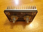
going to use two Fotek SSR-100's
https://www.amazon.com/gp/product/B07PFDJQLV
their data sheet is about as useful as a turd-flavored lollipop http://www.fotek.com.tw/pdf/SSR-DD.pdf
Anyhoooo........
anyone have actual experience with the Fotek brand. I know Sam is using SSR's for the downriggers, however brand was not specified.
the trigger side draws 12mA, which should allow extended over-nights when running on the house batteries
plan on two of these sitting on top of heat sinks triggered on the accessory circuit side of the key switch. This is primarily for when I forget to turn the 0-1-2-both battery switch to off
one SSR will be fed from the starter terminal and will power the cabin lights, docking lights, the courtesy lights, swim lights, etc. there is a 50 amp circuit breaker at the battery feeding the 8 AWG cable up to this.
the engine, ignition feed and the accessory feed will be controlled by the 0-1-2-both battery switch
ignition side of the switch is powering VF4 relays at the engine for fuel/start/ignition coil/start interlock, and two VF4 relays at the dash powering nav lights, horn and dash lights. the ignition switch is fed by the 10 AWG wire running back to the engine in the original harness to a 50 amp circuit breaker.
the second one will be fed by the house batteries directly via a 4 AWG cable that cable goes back to a 100 amp breaker at the batteries. this will power the stereo, amp, washdown pump, inverter for the wife to plug in a hair drier or straightener (or a laptop). there will also be cabin lighting and ventilation fans. the trigger side will be fired by the accessory signal from the switch. that way if I forget the amp or inverter on, they go off when I pull the key from the ignition.
Bilge pump is wired so that the Auto side goes straight thru to the battery buss, and the manual side goes thru the accessory side power. this small battery buss goes thru the 0-1-2-both switch, however I may move that to battery hot for times when anchored and the battery switch is on "off"
Blower is wired to the battery buss after the 0-1-2-both switch
each circuit has appropriately sized ETA circuit breakers (new)
I know that a suppression diode is sometimes needed to de-energize the SSR's. I also know thru reading that some SSR's have gone up in spectacular flames when run at the higher end of their rating. the solder melts off the mother board and then the trace burns up in a glorious release of magic smoke
Any one see a flaw?
if they simply fail on the water, my current plan is simply move the wire over.
My backup is a pair of 225 amp Trombetta contactors https://www.trombetta.com/wp-content/uploads/2019/07/bear-family.pdf, however at 7.7 ohms, they would draw a bit of power (about 1.7 amps)
I sketched it up in the attached PDF
View attachment wiring.pdf


