jay_merrill
Vice Admiral
- Joined
- Dec 5, 2007
- Messages
- 5,653
I often see comments about the older OMC control boxes that lead me to believe that there is a lot of misunderstanding about them. In order to help iboats members understand these units, I decided to dig out some of mine and take pictures of them, showing the controls and their key features.
Just because of time issues, I'll do this in installments, revising this thread as I go.
Shipmaster/Simplex Controls
The first thing to know, is that the Johnson version of these control units was named "Shipmaster" and the Evinrude version was named "Simplex." As with OMC products in general during that time period, there is very little difference between the two. In fact, the differences are limited to paint color and badging.
There were also three basic versions of these units. The first was somewhat smaller in size and had rounded shoulders on the control casing. The later units were larger, had square shoulders and came in two types, one of which took the older, Type 400 cables (as did the original units), while the other used Type 479 cables. The type 479 cables and associated control units were made available in 1979.
Original, Type 400 Control Box

This photo shows the control unit as it appears when assembled. This particular one happens to be a Johnson Shipmaster. I don't know the actual production span, but I believe it was from the fifties to the early sixties. If anyone can update me on this info, please do so.

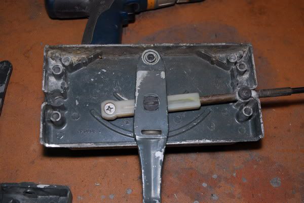
In this photo, the box has been opened and the outer half is placed to the right. This the half that holds the gear shift handle, while the other half (left) holds the throttle lever. The black piece is a spacer that separates the halves.


These two photos provide a closer look at the control box halves and the levers. The upper photo is the outer, gearshift side and the lower photo is the inner, throttle side. Note the geared ends on the levers, which differs from the later, square shoulder models.

In this photo, the plastic end fittings that are inserted into the control box are shown. They are mounted on Type 400 cables, via allen head set screws. You can not see the set screws in the photo, because when tightened, they are recessed into the plastic piece.

In this final photo, the engine end of the cables can be seen. One cable end has a set screw mounted fitting (throttle side) and the other shows the bare wire, with the gearshift end fitting removed. Those with sharp eyes and knowlege of the cables, may notice that the ones in my photo have thicker casings than the Type 400 cables now available.
ignore any references to Part 2 and Part 3. The three threads have been combined as a single resource. It works better this way.
???
Just because of time issues, I'll do this in installments, revising this thread as I go.
Shipmaster/Simplex Controls
The first thing to know, is that the Johnson version of these control units was named "Shipmaster" and the Evinrude version was named "Simplex." As with OMC products in general during that time period, there is very little difference between the two. In fact, the differences are limited to paint color and badging.
There were also three basic versions of these units. The first was somewhat smaller in size and had rounded shoulders on the control casing. The later units were larger, had square shoulders and came in two types, one of which took the older, Type 400 cables (as did the original units), while the other used Type 479 cables. The type 479 cables and associated control units were made available in 1979.
Original, Type 400 Control Box
This photo shows the control unit as it appears when assembled. This particular one happens to be a Johnson Shipmaster. I don't know the actual production span, but I believe it was from the fifties to the early sixties. If anyone can update me on this info, please do so.
In this photo, the box has been opened and the outer half is placed to the right. This the half that holds the gear shift handle, while the other half (left) holds the throttle lever. The black piece is a spacer that separates the halves.
These two photos provide a closer look at the control box halves and the levers. The upper photo is the outer, gearshift side and the lower photo is the inner, throttle side. Note the geared ends on the levers, which differs from the later, square shoulder models.
In this photo, the plastic end fittings that are inserted into the control box are shown. They are mounted on Type 400 cables, via allen head set screws. You can not see the set screws in the photo, because when tightened, they are recessed into the plastic piece.
In this final photo, the engine end of the cables can be seen. One cable end has a set screw mounted fitting (throttle side) and the other shows the bare wire, with the gearshift end fitting removed. Those with sharp eyes and knowlege of the cables, may notice that the ones in my photo have thicker casings than the Type 400 cables now available.
ignore any references to Part 2 and Part 3. The three threads have been combined as a single resource. It works better this way.
???
Last edited by a moderator: