Shift interrupter switch.

Tzimm007

Cadet
Joined
Jul 23, 2022
Messages
10
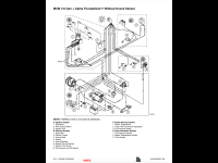
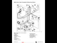
Hi guys. I have been looking through all the threads about these switch’s. I have a early 2000 I believe 5.7L LX. It has the thunder bolt ignition. I checked the continuity on the switch with an ohm meter and the switch is good.
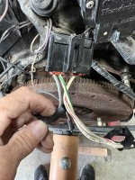
My switch is wired direct though. Green/white to green/white and black to black. I have seen the diagrams on here about some type of block both wires are ran too but mine doesn’t have that. My question is could that be the reason SIS is not working?? TIA please direct me if this has already been discussed!
 

achris

More fish than mountain goat
Joined
May 19, 2004
Messages
27,468
Hello and welcome aboard.

The block is just a terminal block, and in essence another failure point.

If the switch isn't working but you have checked it with a multimeter, then the lever may be out of adjustment. With the roller (a) centred
1658644658552.png
you should only be able to move the roller away by 3mm before the switch closes. If it doesn't close by 3mm of movement, bend the arm until the right distance is obtained.

Chris.......

One of the most useful pieces of information on a Mercruiser is the engine and drive serial numbers. When you post a question it would be appreciated if you add the model, year and serial number to the first post of any thread. That way anyone trying to answer your question can look up and see exactly what we are dealing with... Also, if you (or a PO) has done any modifications that take the package away from 'standard', they would also be nice to know about...

Cheers.
 

Tzimm007

Cadet
Joined
Jul 23, 2022
Messages
10
Thanks Chris! I’ll get the serial number.
I don’t think it’s a mechanical issue. The switch operates as it should mechanically. I know I still need to adjust it because when I put it in reverse it depresses the switch all the way but does not kill the motor.

So the switch should operate as it’s designed if it’s wired direct and not using the block if I understand you correctly?
The boat had been sitting for five or six years when I got it so the pack rats did a number on some of the wiring. I’ve been chasing down chewed and cut wires through this whole process. The 4.3 L motor that was in the boat was no good and I replaced it with a complete 5.7 pull out that was all working correctly. I had to change out the SIS though because the boat the motor came out of had a bravo out drive that utilized a different switch system.
What I was hoping was that all of the wiring for that switch is in the motor harness and doesn’t have anything running up to the ignition on the dash that could be damaged.
 

Scott06

Admiral
Joined
Apr 20, 2014
Messages
6,727
Thanks Chris! I’ll get the serial number.
I don’t think it’s a mechanical issue. The switch operates as it should mechanically. I know I still need to adjust it because when I put it in reverse it depresses the switch all the way but does not kill the motor.

So the switch should operate as it’s designed if it’s wired direct and not using the block if I understand you correctly?
The boat had been sitting for five or six years when I got it so the pack rats did a number on some of the wiring. I’ve been chasing down chewed and cut wires through this whole process. The 4.3 L motor that was in the boat was no good and I replaced it with a complete 5.7 pull out that was all working correctly. I had to change out the SIS though because the boat the motor came out of had a bravo out drive that utilized a different switch system.
What I was hoping was that all of the wiring for that switch is in the motor harness and doesn’t have anything running up to the ignition on the dash that could be damaged.
If you are using a bravo ignition module since it was a bravo tear out the shift interrupt will not work

Bravo drives with a cone clutch do not require shift interrupt I think you need to swap a alpha module

Did you get rid of the belt driven water pump as well ? Not sure if that can be run in series with the pump in the drive on an alpha
 

achris

More fish than mountain goat
Joined
May 19, 2004
Messages
27,468
If it's Thunderbolt then the switch connects directly to the distributor sensor, and has no interaction with the ignition module. It should work regardless... MPI, different ball of wax...

Chris...
 

Tzimm007

Cadet
Joined
Jul 23, 2022
Messages
10
Thanks Scott, that would probably explain the trouble we we’re having with the ignition to.
If I bypass the distributor and run a wire from the switch to the negative side if the coil would that work??
Thanks!
 

nola mike

Vice Admiral
Joined
Apr 22, 2009
Messages
5,410
nks Chris! I’ll get the serial number.
I don’t think it’s a mechanical issue. The switch operates as it should mechanically. I know I still need to adjust it because when I put it in reverse it depresses the switch all the way but does not kill the motor.

So the switch should operate as it’s designed if it’s wired direct and not using the block if I understand you correctly?
The boat had been sitting for five or six years when I got it so the pack rats did a number on some of the wiring. I’ve been chasing down chewed and cut wires through this whole process. The 4.3 L motor that was in the boat was no good and I replaced it with a complete 5.7 pull out that was all working correctly. I had to change out the SIS though because the boat the motor came out of had a bravo out drive that utilized a different switch system.
What I was hoping was that all of the wiring for that switch is in the motor harness and doesn’t have anything running up to the ignition on the dash that could be damaged.
Super simple. The switch just grounds the grn/wht wire to the block. That's it.
 

Tzimm007

Cadet
Joined
Jul 23, 2022
Messages
10
If it's Thunderbolt then the switch connects directly to the distributor sensor, and has no interaction with the ignition module. It should work regardless... MPI, different ball of wax...

Chris...
I’ll get the serial number for the motor when I get home today.
The green and white wire running from the switch does run into the front side of the distributor.
Can I bypass all that and just run a wire from the switch to the ground side of the coil??
 

Tzimm007

Cadet
Joined
Jul 23, 2022
Messages
10
nks Chris! I’ll get the serial number.

Super simple. The switch just grounds the grn/wht wire to the block. That's it.
That’s what I was thinking but it does run into the front of the distributor first.
If I just run grn/wt side of the switch directly to the negative side of the coil, would that work??
 

nola mike

Vice Admiral
Joined
Apr 22, 2009
Messages
5,410
Thanks Scott, that would probably explain the trouble we we’re having with the ignition to.
If I bypass the distributor and run a wire from the switch to the negative side if the coil would that work??
Thanks
Seems like a bad idea. You wouldn't be disabling the module, which will be trying to switch against voltage spikes at the coil
 

Tzimm007

Cadet
Joined
Jul 23, 2022
Messages
10
Seems like a bad idea. You wouldn't be disabling the module, which will be trying to switch against voltage spikes at the coil
Ok where is the disconnect. Why is it not communicating the way it should be to cause the interrupt? From what I can see all of the wire on the motor harness is good the only differences that it has an actual switch now. Could there be something in the distributor that’s not allowing continuity?
 

nola mike

Vice Admiral
Joined
Apr 22, 2009
Messages
5,410
I checked the continuity on the switch with an ohm meter and the switch is good.
My switch is wired direct though. Green/white to green/white and black to black.
What exactly is the issue you're having? Sounds like the switch is closing correctly? The green/wht wire should be grounded when the switch is closed. You can check and see if the wire is grounded at the distributor when you close the switch.
 

Scott06

Admiral
Joined
Apr 20, 2014
Messages
6,727
Ok where is the disconnect. Why is it not communicating the way it should be to cause the interrupt? From what I can see all of the wire on the motor harness is good the only differences that it has an actual switch now. Could there be something in the distributor that’s not allowing continuity?
it was my understanding ( could be completely wrong) that bravo modules do not have shift interrupt feture. I heard thus through michigan motorz when i did my repower seven years ago. I did not want to use the Delco EST that came with a partial engine package so they sent me a thunderbolt distributor and bravo ignition module when I called them back and said I have an alpha they sent me a different module because the bravo won’t work with an alpha shift interrupt. If u have an alpha module can be v6 try it out.
i was able to run my engine on the v6 module on a pallet. By my wiring diagram wht/grn goes through shift interrupt to ground. I think with bravo module it ran with shift interrupt wires in harness jumpered togther…but didnt test shift interrupt
 

nola mike

Vice Admiral
Joined
Apr 22, 2009
Messages
5,410
it was my understanding ( could be completely wrong) that bravo modules do not have shift interrupt feture.
The shift interrupt with the TB ignitions works essentially the same as it does with points. The green/wht is the trigger wire from the sensor. When running, the sensor is sending a pulsed signal based on the speed of the rotor. The ignition module then sends a pulsed ground to the coil. When grn/wht is grounded, you are no longer sending a pulsed signal to the module, so the module is no longer sending the signal to the coil, so no spark. The module is dumb in that it doesn't know why it isn't getting the signal from the sensor.
 

Scott06

Admiral
Joined
Apr 20, 2014
Messages
6,727
The shift interrupt with the TB ignitions works essentially the same as it does with points. The green/wht is the trigger wire from the sensor. When running, the sensor is sending a pulsed signal based on the speed of the rotor. The ignition module then sends a pulsed ground to the coil. When grn/wht is grounded, you are no longer sending a pulsed signal to the module, so the module is no longer sending the signal to the coil, so no spark. The module is dumb in that it doesn't know why it isn't getting the signal from the sensor.
Yes makes sense but why would merc have a alpha and bravo module as separate parts? I get it for bigger engines but 4.3, 5.0, 5.7 doesn’t make sense unless something is different

look up a bravo wiring diagram green white is constant hooked to ground vs going through shift interrupt on an alpha.
 

nola mike

Vice Admiral
Joined
Apr 22, 2009
Messages
5,410
Yes makes sense but why would merc have a alpha and bravo module as separate parts? I get it for bigger engines but 4.3, 5.0, 5.7 doesn’t make sense unless something is different

look up a bravo wiring diagram green white is constant hooked to ground vs going through shift interrupt on an alpha.
There are a ton of module part numbers that I found, though don't see them broken down by outdrive. Same with wiring diagrams. Which ones are you looking at? And green still shouldn't be grounded, should be the same just without the SIS leg, only from module to distributor.
 

Tzimm007

Cadet
Joined
Jul 23, 2022
Messages
10
Hey guys sorry I just got back from the movies with my kiddos. I’m trying to follow along with this but it is all brand new to me so forgive any ridiculous questions. I took a few minutes to see if I could find a number on that motor and I didn’t see anything. Is there a universal place where the serial numbers are on the motor? The gentleman that helped me put the motor in said there was something different about the Alpha‘s and the bravos for the shift interrupt. I know that’s been mentioned in this thread also. I don’t remember what he said though.
Did I see something about switching to an alpha module??
 

Tzimm007

Cadet
Joined
Jul 23, 2022
Messages
10
There are a ton of module part numbers that I found, though don't see them broken down by outdrive. Same with wiring diagrams. Which ones are you looking at? And green still shouldn't be grounded, should be the same just without the SIS leg, only from module to distributor.
The grn/wht wire runs to the distributor. Then I wanna say there is a purple and gray wire coming out of the distributor running to the coil.
 

Scott06

Admiral
Joined
Apr 20, 2014
Messages
6,727
There are a ton of module part numbers that I found, though don't see them broken down by outdrive. Same with wiring diagrams. Which ones are you looking at? And green still shouldn't be grounded, should be the same just without the SIS leg, only from module to distributor.
alpha bravo wiring diagrams and clip of modules listed in electrical parts list for 5.0/5.7 carb engines . the wiring in the 4.3 alpha is whats on my boat, kept the harness when i swapped 4.3=>5.0 just changed module
Of course different years could be different but all the TBV modules ive seen denote alpha or bravo
 

Attachments

  • E2964E80-3186-4376-BFAA-40257A1DCED3.png
    E2964E80-3186-4376-BFAA-40257A1DCED3.png
    460.9 KB · Views: 10
  • 043181F4-19F2-4E4B-A7E9-597B53A037F6.png
    043181F4-19F2-4E4B-A7E9-597B53A037F6.png
    480.1 KB · Views: 10
  • 54A05A82-E138-4B47-AE70-6387A991AE7B.png
    54A05A82-E138-4B47-AE70-6387A991AE7B.png
    480.4 KB · Views: 10

Tzimm007

Cadet
Joined
Jul 23, 2022
Messages
10
This is the 4.3 distributor. Would that possibly be the module I could change if the 5.7 would plug into it? That number is on the 4.3. Would it be in the same place on the 5.7? Back of the motor above the bell housing?
6BBD45E9-6132-402D-821D-1FF0951EBA53.jpeg
 

Attachments

  • 2F811984-29E3-41D9-8E98-F69047CFCF18.jpeg
    2F811984-29E3-41D9-8E98-F69047CFCF18.jpeg
    1.3 MB · Views: 4
  • image.jpg
    image.jpg
    1.4 MB · Views: 4
Top