Safe, Economical, Automatic 12/24 volt switching

Bubba1235

No longer on Forums
Thread starter
Joined
May 25, 2008
Messages
588
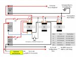
Had a bit of time on my hands this afternoon so I reviewed all the comments from everyone and then designed a fully automatic switching system for 3 batteries (one engine battery, two house batteries) for 12 / 24 volt operation and allowing ALL batteries to be combined for engine starting and battery charging. Note: This assumes you have a real charging system, not a stator low amperage system. It will still combine the batteries for starting purposes but stator output is very limited for charging.

NewWire3.jpg


I've tried to design the system to be extremely safe and have used Sealed Solenoids there by meeting ABYC and USCG requirements for "ignition protected". These solenoids are sold by many Marine distributors and you can buy them from your favorite distributor but I've found a cheaper source. For those that feel the desire to check the specs. on them I will also provide a link to it. Note: Solenoids should be mounted vertically with the coil terminals on top as shown in the diagram.

If you are the nervous type or just like going to the back of the boat to switch things around you can replace Solenoid 3 (S3) with an off the shelf Perko style On/Off switch. Simply remove the coil wiring and connect the load leads to the Perko switch.

A bit about safety, many had issues with using solenoids and/or relays to do the switching asking "what if" this or that fails. If you study the diagram you will see that S3 can NOT energize (completing the circuit to tie the batteries together) unless both S1 and S2 have changed state. Turning on the ignition switch of the boat powers the solenoid coils of S1 and S2 and only after they change state does S3 have coil voltage applied. That happens in the blink of an eye time wise, unless there is a fault. Additionally note there is a fuse between House batteries and the rest for the circuit. Should a space born meteor fall from the sky and destroy a solenoid and melt all the wiring into a molten mess, the fuses would blow and break the circuit. I spec. a 200 Amp Fuse based on using three batteries during engine cranking. This is a ANL ignition protected fuse that has a time delay for current "in rush". (Made by Blu Sea - Sold by many)

Additionally I have included a Buck Booster to supply 12 volts to lights, fish finder, etc. that draws it's power from the house batteries and / or the alternator when the engine is running. It's advantage is that it places it's load on BOTH house batteries regardless of being in 12 volt or 24 volt mode AND prevents uneven discharge and wear associated with tapping a single battery. The booster can handle 8 amps continuous and 10 amps "surge". I know some might consider that over kill and for those folks it can be taken out of the circuit and simply tap House battery 2 for 12 volt supply. Do NOT tap House battery 1 for this purpose!


I welcome any and all comments and if it meets with everyone's approval I'd like to see this post made a "sticky" instead of having to go look for it each time it's needed. :)


Just in case Photbucket goes away I'm including the drawing as an attachment.
 

Attachments

  • NewWire3.jpg
    NewWire3.jpg
    81.1 KB · Views: 0

Auger01

Petty Officer 1st Class
Joined
Aug 15, 2009
Messages
201
Re: Safe, Economical, Automatic 12/24 volt switching

Nice drawing. What software did you use for that?

One problem I see is that S3 will pick up a ground from house batt 1 via the blue wire and change state as soon as power is applied from the ignition switch regardless of S2 position. That makes S3 superfluous. I think two of the S1 type relays interlocked togeather might be the way to do what you want to do.

Is this purely an academic problem or are you planning to eventually install a version of this setup?
 

fishrdan

Admiral
Joined
Jan 25, 2008
Messages
6,989
Re: Safe, Economical, Automatic 12/24 volt switching

I don't see how S3 will close since there isn't a path to engine ground for S3 coil's negative terminal, (unless S3 is closed). I looked over the diagram and it's not the way I'd do it since the 24V bank needs to be decoupled from engine ground, or 24V will be sent to everything on the 12v circuits. I'd figure out how to do it with the bottom house battery permanently tied to engine ground, then the top house battery cutting over to a series connection for 24V, or a parallel connection for charging.

How would someone emergency start the engine if configured with the current diagram, if the start battery is completely dead?
 

fishrdan

Admiral
Joined
Jan 25, 2008
Messages
6,989
Re: Safe, Economical, Automatic 12/24 volt switching

I know that part is a little confusing and is hard to explain in words but I'll give it a go. If you look you will see that the positive of House batt. 1 and the Engine batt. positive are permenently tied together. (Physically, not electrically until all solenoids change state.) Electrically, there is no difference between the positive terminals of both batteries and that means the voltage from the ignition switch can provide voltage to the coils but only in respect to House batt. 1 until S3 is energized and completes the circuit).

I see what you had going on, house batt #1 was providing ground to the coil, not engine ground. The old diagram would have worked.

With the reworked diagram house batt #1 and #2 have to be paralleled before the house batt grounds will be coupled to engine ground,,, with a 12V signal.

I'm going to play Murphy's advocate... If house batt #1 and #2 are stuck in series because S1 is not tripping, S3 can still trip, this time with a 24V ground reference, and a path the send 24V to the engine until a fuse blows. I know this shouldn't happen if everything is working properly, but I prefer to error on the side of caution... I've had several high current solenoids, (marine, HVAC) fail by either fusing the contacts or the coil not firing, even a loose or corroded wire could cause switching issues.

There's probably a solution by swapping around the solenoid + - leads, so S3 will only apply after S1 has applied and paralled the house batteries. (I have to go help the kiddies now, but will look at it later....)
 

fishrdan

Admiral
Joined
Jan 25, 2008
Messages
6,989
Re: Safe, Economical, Automatic 12/24 volt switching

How about this...

S3 coil + wire going to house batt#2 + terminal, S3 coil - wire going to house batt #1 negative terminal. When the house bank is in series S3 can't trip as S3 coil terminals are at the same potential, shorted together. When S1 applies it first breaks the 24V series connection and then combines the house battery + terminals, completing the circuit for S3 through house batt #1.

Heck, do the same thing for S2. S2 coil + wire going to house batt#2 + terminal, S2 coil - wire going to house batt #1. S2 won't apply and parallel the house battery grounds until S1 has broken the series connection and paralleled the house batt positive terminals.

If S1 opens the connection between house batt #1 and #2, or fails to make the connection for any reason, S2 and S3 will either open or stay open.
 

bruceb58

Honorary Supreme Mariner
Joined
Mar 5, 2006
Messages
30,834
Re: Safe, Economical, Automatic 12/24 volt switching

If you ever try to start your engine with the house batteries, you will blow your fuses in a heartbeat.
 

bruceb58

Honorary Supreme Mariner
Joined
Mar 5, 2006
Messages
30,834
Re: Safe, Economical, Automatic 12/24 volt switching

Yes, you will probably be ok with 200A fuses. By the way, you can't calculate the current based on 12V, you have to take into account the voltage drop of the cables(both of them and your solenoids) when figuring out your current. As the voltage drops to the starter, it will draw more current. It is not exactly linear but it is more.
 

bruceb58

Honorary Supreme Mariner
Joined
Mar 5, 2006
Messages
30,834
Re: Safe, Economical, Automatic 12/24 volt switching

Myself I'm a fan of using welding cable as the strands are much finer making them easier to bend and can carry more current for a given size.
That's not true unless the actual cross section is different which it shouldn't be if the gauge is the same. Better off using marine cable that is tinned. You are working with DC. There are no skin effects with DC if that is what you are thinking.

At 50 feet with 2 gauge cable, you will have 2.25V drop in your cables @ 140A

You 140A calculation is while the starter is running under load. The startup current is way higher.
 

fishrdan

Admiral
Joined
Jan 25, 2008
Messages
6,989
Re: Safe, Economical, Automatic 12/24 volt switching

I charge my 24V bank similar to what Bubba is working on, break the 24V bank and parallel it over to 12V. I have a 50 amp manual reset breaker on one of the trolling motor batteries and I've never popped the breaker while starting the engine, with all 3 batteries supplying power to crank over the engine (batteries switched over for charging). I've even started the engine off the paralleled house bank by mistake, and did not popped the 50 amp manual reset breaker. This is on a 140HP Mercruiser with a gear reduction starter, so the starter current is lower than a V8 with an old style heavy duty starter, but If I'm not popping a 50 amp breaker, I doubt 2- 200 amp fuses would blow starting a V8.

One thing I noticed, the house bank is going to be combined with the start battery as soon as the ignition is in the run position. Since the run position is also applied while starting the engine, severely depleted house bank batteries would present a big draw on the electrical system and make the engine harder to start. A VSR would solve that issue and keep the house batteries from charging until the alternator is kicking out around 13.7V.

When I have depleted house batteries to charge, I start the engine first, then switch it over to charging. Once switched over to charging the engine idle RPM drops 50-75RPM under the alternator's load. It's a 100 amp alternator that kicks out around 50 amps at idle...

[Edit: About using the VSR I mentioned. When I'm recharging the trolling motor batteries at idle the engine voltage drops to around 13V, so I'm not sure the VSR would work, or it would be going nuts switching back and forth. At high RPM the alternator would probably get the voltage high enough to keep the VSR happy, but I can't do that with the high output alternator, too much output.]
 

bruceb58

Honorary Supreme Mariner
Joined
Mar 5, 2006
Messages
30,834
Re: Safe, Economical, Automatic 12/24 volt switching

[Edit: About using the VSR I mentioned. When I'm recharging the trolling motor batteries at idle the engine voltage drops to around 13V, so I'm not sure the VSR would work, or it would be going nuts switching back and forth. At high RPM the alternator would probably get the voltage high enough to keep the VSR happy, but I can't do that with the high output alternator, too much output.]
The VSR would be perfect for that. There is some built in hysteresis so it would not be oscillating. It will switch in and out but eventually the voltage would get up to a level where it would stay constantly on. I did a similar thing hooking up a house battery in a horse trailer to my pickup truck.
 

bruceb58

Honorary Supreme Mariner
Joined
Mar 5, 2006
Messages
30,834
Re: Safe, Economical, Automatic 12/24 volt switching

I agree that would work but it comes down to how complicated to make it. The more components, the more to go wrong sort of thing. I've been playing with the idea of building a system with a small / cheap ($35) computer to drive SCR's (silicone controlled rectifier) to do all the switching and manage charging. I think I can do it for around $200 - $250. Not certain it's worth the effort though.
SCRs would have too much voltage drop across them and I don't think they will turn off when used for DC. I believe they latch. That is why they are mainly used for AC circuits. Power FETs are what would need to be used. By the way it's silicon, not silicone.
 

bruceb58

Honorary Supreme Mariner
Joined
Mar 5, 2006
Messages
30,834
Re: Safe, Economical, Automatic 12/24 volt switching

Yes, if the circuit is designed properly. Point being, they can be used as high current, low cost DC switchs. Maybe if I get time this weekend I'll put a drawing together and you can look it over.
Why wouldn't you use FETs? That is what ACRs use.
 

Don S

Honorary Moderator Emeritus
Joined
Aug 31, 2004
Messages
62,321
Re: Safe, Economical, Automatic 12/24 volt switching

Seems to me, if a 12/24 switching setup was so, economical, automatic, and SAFE, that the trolling motor companies, or marine electrical companies like Bluesea, would be all over making one. They aren’t, and I wonder why?

Could it be that if you misplace one wire you could trash all your electronics on the boat, and your motors electrical system?
(serious bummer if you have EFI and blow your ECM)

I bet there is a large percentage of people that visit this forum that doesn't really understand even the basics of how electricity works, and what voltages can kill what systems. Sure they may ask if you can combine the two with a simple switch, but they are hoping there is an EZ button involved and a $10 switch to do it with, but this system you are putting together is NOT for those without out some serious knowledge of DC electrical systems.
 
Top