Routing transducer wires on trolling motor mount

gnrboyd

Petty Officer 2nd Class
Joined
Oct 18, 2007
Messages
157
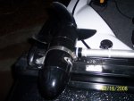
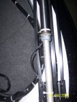
I have a 93 Evinrude foot control trolling motor that I will be mounting an Eagle puck style transducer to. I believe the typical install is to route the cable up the shaft using wire ties and then proceed down the cable to the foot control using electrical tape or wire ties, and then down the power wire to the plug. There will be extra wire so I was thinking I would need to drill a hole in or near the bow panel to hide the extra wire. I then would drill a hole where the unit will be mounted for the transducer/power cable to hook to the unit.​

Am I correct in my assumption that this is the typical install? If not, what are my other options?​

If I do proceed with the above method, I'm a little uncertain of the specifics on when the transducer cable leaves the trolling motor power cord and enters the bow panel area. Do I run the transducer cable all the way to the plug or do I stop a certain distance from the plug. How much extra cable do I need to leave out? I would assume just enough so I can unplug the trolling motor recepticle without putting any tension on the transducer cable.​

Any insight on this would be appreciated.​

Thanks!​

By the way.... the boat is a 92 Sea Nymph Fishin Machine FM 160 / 50 Evinrude.​
 

Texasmark

Supreme Mariner
Joined
Dec 20, 2005
Messages
14,780
Re: Routing transducer wires on trolling motor mount

I have just such a rig but I don't remember all the particulars you question. I am in the house in my skivvies but later on today when I go out I will see what my rig is and tell you. The TM is Motorguide and the DF is Eagle Cuda 168 wide sceen.

I can tell you this for now.
The transducer is bullet shaped and has a nice mounting surface which conforms nicely to the round bottom of the TM being held in place with a large SS clamp....like you would have on your after market radiator hose in a car only much bigger in diameter.

The wires go up the shaft as you surmised secured with tie wraps. They leave the shaft at the top of the mounting yoke and flow down with the yoke being secured there a couple of times (Motorguide provided a couple of holes for that.....seems someone did it before or the designer was thinking ahead). A little service loop at this junction would help if you choose to run your TM deeper in the water after you complete the rigging. If you wire it up with the TM all the way down, then expect a service loop if you readjust it for shallower running.

The TM has a 3 pronged bulkhead mounted plug and as you said, you just leave enough slack in that power wiring to allow for raising and lowering the TM.

What I don't remember is how the DF wiring is routed and connected to the bulkhead. Course on my boat there is no real bulkhead. Just the alum bow escutcheon that exists forward and slightly higher than the front deck where my pedestal seat is located.

Mark
 

gnrboyd

Petty Officer 2nd Class
Joined
Oct 18, 2007
Messages
157
Re: Routing transducer wires on trolling motor mount

I'm not certain, but it sounds like your set up does not have the transducer wire secured to steering cable and power cable. It sounds as if your transducer wire leaves the motor at the head or at the bracket that holds the shaft. If that is the case, it seems like you'll have a little bit of slack wire flopping around because you need it to allow for raising and lowering the motor. Did I misunderstand?​
 

Silvertip

Supreme Mariner
Joined
Sep 22, 2003
Messages
28,771
Re: Routing transducer wires on trolling motor mount

There really is no need to have the transducer cable run all the way to the foot pedal. When you get to the head of the trolling motor, you can run the transducer cable directly to the area where the locator will be mounted, leaving enough slack to allow the motor to be stored. This assumes of course that you have a sissor style motor mount. The Power lead from the locator can be routed anywhere since it has nothing to do with the troller.
 

gnrboyd

Petty Officer 2nd Class
Joined
Oct 18, 2007
Messages
157
Re: Routing transducer wires on trolling motor mount

My thinking on running the cable along side the control cable all the way to the power plug was to just keep the transducer cable more protected. If I run it down to near where the plug is, I can drill hole in my dash panel somewhere close to the plug and will only have a short amount of cable exposed. I believe that is how my last boat was wired if I remember correctly. (I wired it but I can't recall how I did it... Hey, I'm over 40 and the CRS is creeping up on me.... CRS= Can't Remember S^%$.)

If I run it from the trolling motor head straight to the gimble mount area, I will have a couple of feet of cable exposed and may run the risk of pinching it in the motor mount or otherwise get in the way.​
 

gnrboyd

Petty Officer 2nd Class
Joined
Oct 18, 2007
Messages
157
Re: Routing transducer wires on trolling motor mount

Anyone else care to explain how their trolling motor transducer is wired up?​
 

Texasmark

Supreme Mariner
Joined
Dec 20, 2005
Messages
14,780
Re: Routing transducer wires on trolling motor mount

My thinking on running the cable along side the control cable all the way to the power plug was to just keep the transducer cable more protected. If I run it down to near where the plug is, I can drill hole in my dash panel somewhere close to the plug and will only have a short amount of cable exposed.​

I went and looked and that was yesterday. Have been busy. Now I forgot which cable came through a hole in the escutcheon behind the DF unit.

Thinking........I know I have cables coiled in a loop and lying on the deck behind the DF unit. Must be the DF power cable that goes through a small hole. The Transducer cable is left intact, initial length and just rolled up and secured.

Mark
 

gnrboyd

Petty Officer 2nd Class
Joined
Oct 18, 2007
Messages
157
Re: Routing transducer wires on trolling motor mount

Mark,

So does your transducer cable run all the way down the steering cable and power cord or does it branch off at the head as Silvertip suggested?

Thanks for checking your motor.
 

ddennis

Petty Officer 1st Class
Joined
Aug 15, 2006
Messages
351
Re: Routing transducer wires on trolling motor mount

I'll take pics of mine tonight and post..I wire tied mine up the shaft, left a little slack where the 2 parts of the shaft meet so it can turn freely. Then all the way down the cable almost to the foot pedal where it then has some slack, with the bulk of the slack hidden in the bow behind the electrical panel. Just enough comes out of there to connect into the finder.
 

Texasmark

Supreme Mariner
Joined
Dec 20, 2005
Messages
14,780
Re: Routing transducer wires on trolling motor mount

No. It comes up the shaft and where the yoke joins the shaft, it makes a U turn and comes down the yoke to the mount that is bolted to the deck. From there it goes over about 6" and makes a looped pile behind the DF unit. You could make a couple of large holes in the deck for in/out and put some kind of cover over it or a large grommet if you don't want to look at the cable piled up on the deck.

Mark
 

gnrboyd

Petty Officer 2nd Class
Joined
Oct 18, 2007
Messages
157
Re: Routing transducer wires on trolling motor mount

Mark,

I'm having trouble visualizing your set up. Is there some loose slack in the cable to allow for raising and lowering the motor?
 

Texasmark

Supreme Mariner
Joined
Dec 20, 2005
Messages
14,780
Re: Routing transducer wires on trolling motor mount

The yoke attaches to the TM shaft with a clamp bracket that allows you to change the depth of the prop in the water. For setting the length of your ducer cable, you need the TM to be in the deepest position you plan to use as this will determine the max length of cable you will need. The ducer cable is tie wrapped to the round shaft of the TM from the ducer up to this clamp and then down the side of the yoke of which the clamp is part of. Like I said, if you raise the prop to a shallower run position, a loop will form at this intersection but that shouldn't be a problem.

The yoke I just mentioned attaches to the deck mounting part of the TM with a pin so that it can rotate (pivot) from the up to down positions. Your ducer cable should be attached to the yoke and exit at this pivot point. There will be no movement from there and hence no additional slack will be needed other that a little service loop.

3 small service loops are necessary:

1. Where the fixed shaft (that the yoke clamps to) and the rotating shaft (that the motor is mounted on) join, so that you can rotate the motor without the cable binding.

2. At the upper end of the yoke where it attaches to the fixed shaft because this joint rotates almost 180 degrees in moving the TM from stow to use positions.

3. At the lower end of the yoke where it pivots likewise and the ducer cable exits for it's trip to your monitor.

I'd send you a picture but I don't have one, haven taken time to learn how to post, and assume one wouldn't be necessary.

I have a Motorguide Brute 67# TM. Possibly you have something different and that is causing the confusion, if it is built differently from mine.

HTH

Mark
 

jevery

Chief Petty Officer
Joined
Jun 16, 2006
Messages
538
Re: Routing transducer wires on trolling motor mount

I'm having trouble visualizing your set up.

I couldn't really figure it out either. With my Minn Kota PowerDrive nearly the entire length of the shaft has to slide through the mount to stow. This would prevent attaching the cable anywhere along that part of the shaft. In my thinking this would result in the wire attached somewhere near the head then a long length of loose wire then an attachment on the shaft near the motor. there would have to be a good amount of slack along the loose section to prevent the wire from catching as the motor spins for steering. I searched the internet for a couple days for pictures or diagrams and never came up with any. I finally went with a through hull installation. Seems to work fine and not a wire in sight.
 

gnrboyd

Petty Officer 2nd Class
Joined
Oct 18, 2007
Messages
157
Re: Routing transducer wires on trolling motor mount

Mark,

I appreciate the time you took to explain your set up. I think its slowly starting to sink in to my thick skull. I guess routing the cable to the pivot point is the key. I'm gonna just have to go look at my motor so I can better visualize it. Its been pretty cold lately and I havn't even wanted to bother with looking at it. I mailed my transmom mount to Eagle to swap for the puck style and am still waiting on it anyway. My motor is older than yours but I think it should be fairly similar. I appreciate you help.

Jevery... I can't shoot through my hull because I have an aluminum boat. Also, my transducer has a temp sensor on it which I can't live without so it has to be in the water. Glad your set up is working for you.

Hopefully by the time I'm ready to buy another boat, all of the trolling motors will have the built in transducer capability and won't be so expensive. (Yea right!...)
 

Texasmark

Supreme Mariner
Joined
Dec 20, 2005
Messages
14,780
Re: Routing transducer wires on trolling motor mount

I couldn't really figure it out either. With my Minn Kota PowerDrive nearly the entire length of the shaft has to slide through the mount to stow. This would prevent attaching the cable anywhere along that part of the shaft. In my thinking this would result in the wire attached somewhere near the head then a long length of loose wire then an attachment on the shaft near the motor. there would have to be a good amount of slack along the loose section to prevent the wire from catching as the motor spins for steering. I searched the internet for a couple days for pictures or diagrams and never came up with any. I finally went with a through hull installation. Seems to work fine and not a wire in sight.

Jevery,

That is not like my TM. When I go from operate to stow, nothing moves but the upper and lower pivot points (pins) of the yoke which rotate. There is no sliding action along the TM shaft. The relationship (distance) between the clamp position and the TM motor do not change.

Only thing about attaching (tie wrapping ducer cable) to the shaft is that if you run shallower than the initial setting (hence loosen the clamp and pull the TM up then secure), one of your tie wraps may be in the way and you will have to either remove it and allow the cable to flop (service loop at upper pivot gets larger), or push it down the shaft out of the way.

Here, the axiom that "a picture is worth a thousand words" has merit. Grin

Mark
 

Texasmark

Supreme Mariner
Joined
Dec 20, 2005
Messages
14,780
Re: Routing transducer wires on trolling motor mount

Mark,


Jevery... I can't shoot through my hull because I have an aluminum boat. Also, my transducer has a temp sensor on it which I can't live without so it has to be in the water. Glad your set up is working for you.

H

Yes you can. The transducer is fed ac voltage but the transducer converts that to sound waves, 50kHz to 200kHz area. Anything solid transmits sound readily hence if you hard mount your puck in the bottom of your boat it has epoxy/alum/water (all solids....as far as sound transmission is concerned) for sound to go through and it will do it readily. No problem.

On temp, I have 2 Eagle Cuda 168's. One at the helm with it's transducer epoxied to the bottom of the boat right in front of the transom on the inside, and the other on the TM.

I have heard folks mention disparities between internal temp sensors and external. Well, I have deliberately conducted tests on my aluminum rig and never have I found them to be off more than 2 degrees F and usually, once I stop and let things stabilize that drops to identical or 1 degree error.

If you want it inside, put it inside in a spot that is in the water when you want to see it and where there are no hull or other obstructions to cause turbulence, hence bubbles which show up as false echo's. In front of the transom is a perfect place.

Mark
 

gnrboyd

Petty Officer 2nd Class
Joined
Oct 18, 2007
Messages
157
Re: Routing transducer wires on trolling motor mount

Hmmmm... I always had heard you couldn't shoot through the hull on aluminum very well. I especially didn't think the temp guage would read correctly.

I already have my transom transducer for my console unit mounted on the outside of the transom. I have a V-hull that would be difficult to get to a spot to mount the transducer because of the front deck so I think I'll stick to the trolling motor mount for the bow unit.

I looked closer at my trolling motor yesterday and I think running my transcuder cable along the steering cable to the foot control and then from there down the power cable and tucking it in on our around the bow panel will work best. When I get my puck transducer back from Eagle and actually install it, I may try the method you describe but it is kind of hard to see if it is going to work without the actual transducer wire to play with.

Thanks for your help!
 

ddennis

Petty Officer 1st Class
Joined
Aug 15, 2006
Messages
351
Re: Routing transducer wires on trolling motor mount

Here's how I did mine, You can see a little slot in the clamp under the shaft where I routed the cable through.. your mount may or may not have it. If you want any other pics let me know.
 

Attachments

  • 100_2802.JPG
    100_2802.JPG
    39.8 KB · Views: 1
  • 100_2805.JPG
    100_2805.JPG
    48.8 KB · Views: 1
  • 100_2807.JPG
    100_2807.JPG
    60.1 KB · Views: 1
  • 100_2811.JPG
    100_2811.JPG
    25.4 KB · Views: 1

Texasmark

Supreme Mariner
Joined
Dec 20, 2005
Messages
14,780
Re: Routing transducer wires on trolling motor mount

Here's how I did mine, You can see a little slot in the clamp under the shaft where I routed the cable through.. your mount may or may not have it. If you want any other pics let me know.

Don't know why you followed your TM drive wiring harness with your ducer cable. My cables to my TM footcontroller and power come off the head of the TM which is at least a foot higher than my yoke that holds the TM to the boat and the point where the pivot occurs and I make the turn on the ducer cable.

Since my foot controller could be anywhere on the front deck, that would say that my ducer cable would be too, flopping all over the place. Oh well, whatever works.

Mark
 

gnrboyd

Petty Officer 2nd Class
Joined
Oct 18, 2007
Messages
157
Re: Routing transducer wires on trolling motor mount

ddennis... Thanks for the photos. I think your method is what I was leaning toward. Instead of using tie wraps, I was thinking of taking a roll of electrical tape and wrapping all the way down the cable and power cord. My only fear is that it might get hot and glue from the tape might get sticky and make a big mess. The tie wraps sometimes leave sharp edges which can cut fishing line and you'd have to use them every few inches to protect the cable.

Mark... I think if it would work, I would prefer your method but I don't think my older motor is will handle this without exposing too much cable to get caught in something. At 60 bucks a pop, I don't want to cut the cable.

Also, in ddennis' solution, the transducer cable follows all the way to the electrical plug so it really doesn't matter if the foot control is moved around. The transducer wire breaks off just before the plug where it enteres the bow panel.

When I actually get my puck transducer from Eagle I will be try to use your method but I think I will have problems and will end up doing it like ddennis.
 
Top