watsbobton
Cadet
- Joined
- May 28, 2015
- Messages
- 24
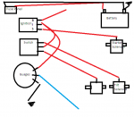
Got 78 OMC Tilt & Selectrim. All my motors/solenoids are wired/getting power. The both ends of wiring harness were pretty rough. Trying to neaten things up, I lost a few connections/labels and I just need some simple reminders on wirings. I'll include some pictures on what I believe I need. Basically going to rewire guages/switches to harness.
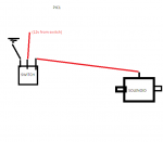
--So for the tilt/trim. The small screw should recieve 12v power to activate solenoid? Is my diagram correct for a switch? (Pic 1)
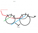
--For wiring guages.. One for +, one for ground, one to recieve? And wire them in sequence? (Pic 2)
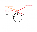
--The 12v of power comes in through harness.. which goes to switch? Again ground.. power.. and 3rd for starter (12v to solenoid?) (Pic 3)
The last issue I have.. I finally got this thing to start, and run great.. but that is with me jumping 12v to the ign coil.. I believe this is due to ungrounded, or problem with key wiring, so hopefully this will fix. If it does not, can I wire 12v to coil from a switch? or is that basically what the key will be doing?
I appreciate the help, I'm pretty handy and not completely useless with electrics, but not an expert.
Thanks!!
--So for the tilt/trim. The small screw should recieve 12v power to activate solenoid? Is my diagram correct for a switch? (Pic 1)
--For wiring guages.. One for +, one for ground, one to recieve? And wire them in sequence? (Pic 2)
--The 12v of power comes in through harness.. which goes to switch? Again ground.. power.. and 3rd for starter (12v to solenoid?) (Pic 3)
The last issue I have.. I finally got this thing to start, and run great.. but that is with me jumping 12v to the ign coil.. I believe this is due to ungrounded, or problem with key wiring, so hopefully this will fix. If it does not, can I wire 12v to coil from a switch? or is that basically what the key will be doing?
I appreciate the help, I'm pretty handy and not completely useless with electrics, but not an expert.
Thanks!!