Overhauling my 1988 Alpha One Drive Train

nola mike

Vice Admiral
Joined
Apr 22, 2009
Messages
5,366
You might do it, he might do, I wouldn't....
I wouldn't, and didn't. Saying that it might have been wired that way for him and it might have worked. At least for a while.
Tell you what. Stick your fingers in a 3 phase socket, then tell me how significant that voltage is (and that's 'only' 220v BTW)....
I'd sooner take the 20k from a plug wire, how about you? I meant how significant is the voltage compared to the current and duration.

It's the voltage that creates arcs, and 400v arcing across contacts designed for 120v is going to eventually lead to burning, and failure. That's isn't an hypothesis, it's a fact.
Not trying to be argumentative. It was an actual question of why that voltage doesn't damage other components. Points you have the condenser. Tach I guess doesn't have the switching that would induce the voltage spike (although presumably in his setup the tach is seeing those voltages). So where does the voltage go in the TB system? The module is still switching via a transistor, so you're still inducing the voltage in the coil primary, right? So the gray wire to the module is still seeing it. Obviously no arcing across a transistor, but I don't know enough about electronics to know how it would be protected.
 

achris

More fish than mountain goat
Joined
May 19, 2004
Messages
27,468
I was in a hurry when I posted the above. Bit more time now.

To explain why a 120v switch will fail when 400v is applied and a transistor or other electronic components will not is to do with the design and operating medium. Electronics designed for a particular voltage will have non conductive material (known as insulators) in and around where the voltage is being conducted. Switch contacts rely on air as an insulator, so the designing is a lot more difficult when dealing with higher voltages. As the voltage increases the propensity to draw an arc as the contacts seperate increases. And if the contact gap is small enough and the voltage high enough, the arc will be spontaneous (think spark plug). But it gets worse. As the contacts arc they start building up carbon, and carbon is very conductive, so as the arcing increases it increases the ease at which the arcing can occur. This is called positive feedback and leads to a 'run away' scenario. It's not long before the switch contacts are effectively constantly closed. If that switch is grounding the negative side of the coil, then the module can never fire it and we have a 'there's no spark' thread...

Chris.
 

Rivergator

Petty Officer 1st Class
Joined
May 7, 2013
Messages
224
I was out for a week, had some eye surgery done and will get more done next week. But in the meantime I tried to get as much information about the white/green shift interrupt connection as I could and I guess we can put this matter to rest now. I contacted Mercruiser several times on different issues and they were extremely helpful. First of all, they have all the records and specs of my particular boat based on the HIN number. They were able to give me all the serial numbers of the entire drive train and how they were delivered on day one. Here are the facts. The engine came from the factory with a TB IV ignition system, which eliminates the speculation that somebody may have upgraded it from a breaker/point system. In italics is a copy of the email response from Mercruiser:

Thank you for your email regarding MerCruiser engine serial number 0B827685. We appreciate the opportunity to respond to your questions.
The shift interrupt switch was only wired to the coil negative when we had points system and in that case the wires on the shift interrupt were not colored like this either. The schematic for Thunderbolt ignition is correct and we fed the module the white/green wire. All Thunderbolt systems were wired this way that is shown in the service manual #7. According to our records your engine originally came with a Thunderbolt IV ignition.
We hope this information is helpful. Should you have any other questions or concerns, please feel free to contact our office at 920-929-5040 between the hours of 7:30am and 4:30pm Monday through Friday, Central Standard Time.


Best regards,
Kim
Consumer Support Specialist
MerCruiser Customer Service


I also spoke with Sam, one of the tech advisers at Mercruiser, he said that it was quite possible that somebody mistakenly or out of ignorance or intentionally connected that wire to the (-) side of the coil, but it does not go there by design. If everything still worked as intended that could very well be possible and speaks well of the robust and tolerant quality of the TB system and nobody really knows why it was wired that way in the first place, even though it may look original because it's been like that for a long time.
To sum it all up, I will most certainly follow the advise of Chris and wire the engine the way it is supposed to be wired. I will make a neat T connector that will splice the shift interrupt switch wire in between the distributor and the ignition amp, just like the wiring diagram says. End of dilemma. Thanks for all your incredible input and constructive discussion.
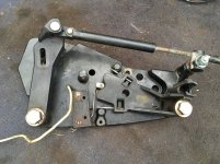
Chris, enclosed is a picture of my shift plate, no terminal block. At least I don't see it. I guess that thing is like a pair of tonsils, not needed. I also tested the shift interrupt switch. It works as intended.
 

Attachments

  • IMG_0707.jpg
    IMG_0707.jpg
    262.6 KB · Views: 11

Rivergator

Petty Officer 1st Class
Joined
May 7, 2013
Messages
224
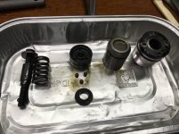
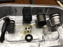
On to my trim system. I found milk in the pump meaning we have a leak for sure. I opened up one of the XD cylinders and the little fluid that was in there was definitely contaminated, maybe not as milky as I saw in the pump, but the rams definitely need to be re-sealed. I am about to order re-seal kit Sierra 18-2649 and I want to make sure that this is the right part for my 1988 Alpha One Gen 1 trim cylinders? Attached are pictures showing the innards of my cylinders. Also what is the preferred fluid to use Oil or Dexron? What was in there now seems to be oil.
 

Attachments

  • IMG_0708 (1).jpg
    IMG_0708 (1).jpg
    136.8 KB · Views: 8
  • IMG_0709 (1).jpg
    IMG_0709 (1).jpg
    125 KB · Views: 8

achris

More fish than mountain goat
Joined
May 19, 2004
Messages
27,468
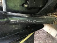
Show us a photo of the ram tube. Do the hydraulic lines both enter at the forward end or is there one at each end?
 

Rivergator

Petty Officer 1st Class
Joined
May 7, 2013
Messages
224
There is one line at each end. The part number is 14035-1
 

Attachments

  • Trim Rams.jpg
    Trim Rams.jpg
    120.8 KB · Views: 5

Rivergator

Petty Officer 1st Class
Joined
May 7, 2013
Messages
224
Well I guess nobody has an answer to any of the questions posted in post #45 and 47.
 

Paintman1960

Petty Officer 2nd Class
Joined
Apr 21, 2021
Messages
153
Well I guess nobody has an answer to any of the questions posted in post #45 and 47.
I was waiting too, but have since found out you can use either oil or Dextron, I read ya can't mix the two tho.
Im doing mine TA real soon, it will all be apart .
Someone correct me if it is wrong info.
 

achris

More fish than mountain goat
Joined
May 19, 2004
Messages
27,468
... I am about to order re-seal kit Sierra 18-2649 and I want to make sure that this is the right part for my 1988 Alpha One Gen 1 trim cylinders?
Overhaul kit is Merc part# -87399A2. Seal kit is Merc part# 25-87400A2.
...Also what is the preferred fluid to use Oil or Dexron? What was in there now seems to be oil.
Merc recommendation is SAE30 non-detergent oil. If you already have ATF, then stay with that.

Chris..
 

Rivergator

Petty Officer 1st Class
Joined
May 7, 2013
Messages
224
Thanks Chris. I think I will spend the money and use the proper OEM power trim and power steering fluid after I make sure I have no leaks in either system (power steering and trim) and everything works as it should. For testing I will use ATF fluid because it is thinner, cleans and flushes everything thoroughly and after everything checks out I will flush out the ATF fluid and do a final fill with the OEM recommended stuff.
 

Rivergator

Petty Officer 1st Class
Joined
May 7, 2013
Messages
224
I was waiting too, but have since found out you can use either oil or Dextron, I read ya can't mix the two tho.
Im doing mine TA real soon, it will all be apart .
Someone correct me if it is wrong info.
I came across this thread posted on 7/2/2012 "What fluid do I use in my alpha one trim pump". It has a lot of good, in depth discussions about that subject. Very educational. Chris says that the Quicksilver power trim and steering fluid is what the factory deems to be the proper, recommended fluid, but Chris also said that it is basically nothing more than 30 weight oil. Now I may change my mind again and put in a good 30 weight oil if it's all the same. That brings up another question though. Can I then use a 30 weight oil in my power steering pump as well?
 

Rivergator

Petty Officer 1st Class
Joined
May 7, 2013
Messages
224
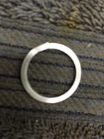
Thanks Chris. So I guess I am all squared away on the fluid. I received my hydraulic ram re-seal kit 25-87400A2 and there is one part in there I don't know what to do with. It's not among the old parts I removed so I guess it may not apply to my Alpha One/Gen 1 application, but if it does then that part was missing in both rams. It's a split ring (see picture) and it may be used in a different application, but out of curiosity does anybody know where this part goes or where it is being used? It is not the fat ring that secures the outer most seal under the clip.
 

Attachments

  • IMG_0714.JPG
    IMG_0714.JPG
    1.5 MB · Views: 2

Rivergator

Petty Officer 1st Class
Joined
May 7, 2013
Messages
224
Well I guess nobody has an idea where that split ring goes. Fortunately in the meantime I found out where it goes. But I have another question and I hope somebody can explain it to me. My ram cylinders are all done and now I am servicing and checking out the trim pump assembly. Motor is excellent and ready to go. Adapter is also in good shape. All internal parts are clean, free and the seals are tight. Just for the sake of enriching my knowledge can anybody explain to me how this pump works and I don't mean electrically but what happens when the motor starts spinning. How is the fluid channeled starting in the reservoir, through the filter up in to the pump and so on. The Alpha One manual #6 page 383 shows a very nice and clear picture of the layout but it does not show how exactly does the fluid flow and gets to the appropriate side of the rams. And the other question is does the pump require 1 or 2 filter elements? Thanks
 

Rivergator

Petty Officer 1st Class
Joined
May 7, 2013
Messages
224
Your lack of responses has motivated me to figure things out myself and I found the answers to my previous 2 posts. But maybe, just maybe somebody can give me some tips here with this one. I am getting ready to repaint my bilge and to my amazement I found out that there is no black bilge paint available. I want to paint the bilge black because the rest of the engine compartment is black. If I cannot find any designated black bilge paint can you recommend a good substitute that is as durable and suitable. What do you think about epoxy garage floor paint or other epoxy floor paint etc.?
Thanks
 

achris

More fish than mountain goat
Joined
May 19, 2004
Messages
27,468
Sorry about the lack of response. I've been away for the last week (work) and it's been hectic.

I like your idea of garage floor paint. đź‘Ť
 

Rivergator

Petty Officer 1st Class
Joined
May 7, 2013
Messages
224
Does anybody know what the factory size hole is for the rear mounts on the inner transom plate? See picture!
Thanks
 

Attachments

  • Transom Plate.jpg
    Transom Plate.jpg
    72.9 KB · Views: 9

Scott06

Admiral
Joined
Apr 20, 2014
Messages
6,451
Does anybody know what the factory size hole is for the rear mounts on the inner transom plate? See picture!
Thanks
No what hardware are you missing ? Its a 1/2” x20 bolt that goes in there so its a clearance hole for that size
 
Top