Overhauling my 1988 Alpha One Drive Train

Rivergator

Petty Officer 1st Class
Joined
May 7, 2013
Messages
224
Nola Mike, I don't know where the terminal block is. The white/green wire that goes to the distributor comes from the ignition amplifier and that is all. The other white/green wire comes from one side of the shift interrupter switch and has a round connector on it (see picture). So it could not have gone to the distributor, because there is no way to connect to it, but must have been connected to a screw connection. The nagging question is WHERE. The other side of the shift interrupter switch has a black wire which is ground. But I don't see any terminal block.
Here is a question to all of you who are very knowledgeable with electronics and electrical systems on boats and cars in general. What would happen (while the engine is running) if the minus pole of the coil comes in contact with ground? And also what would happen if the plus pole of the coil comes in contact with ground?
achris, you posted a comment, but it is blank????
 

nola mike

Vice Admiral
Joined
Apr 22, 2009
Messages
5,364
Nola Mike, I don't know where the terminal block is. The white/green wire that goes to the distributor comes from the ignition amplifier and that is all. The other white/green wire comes from one side of the shift interrupter switch and has a round connector on it (see picture). So it could not have gone to the distributor, because there is no way to connect to it, but must have been connected to a screw connection.
Is it physically long enough to reach? Are you sure that isn't a cover over the screws on the distributor?
The nagging question is WHERE. The other side of the shift interrupter switch has a black wire which is ground. But I don't see any terminal block.
Follow the black wire. If that wht/grn doesn't go to the distributor it may go to the terminal block. I'll try to get a look at my system tomorrow
Here is a question to all of you who are very knowledgeable with electronics and electrical systems on boats and cars in general. What would happen (while the engine is running) if the minus pole of the coil comes in contact with ground?
The ignition won't fire and the engine will stall
alsoso what would happen if the plus pole of the coil comes in contact with ground?
Bad things. Don't do that. Blow a fuse best case.
 

achris

More fish than mountain goat
Joined
May 19, 2004
Messages
27,468
Nola Mike, I don't know where the terminal block is. The white/green wire that goes to the distributor comes from the ignition amplifier and that is all. The other white/green wire comes from one side of the shift interrupter switch and has a round connector on it (see picture). So it could not have gone to the distributor, because there is no way to connect to it, but must have been connected to a screw connection. The nagging question is WHERE. The other side of the shift interrupter switch has a black wire which is ground. But I don't see any terminal block.
The original ignition sensors had a couple of screw terminals, and that's where the white/red and the white/green connected. It was even written on the sensor which terminal was which. By the sound of it, and a photo or 3 would be really helpful here, at some stage the sensor has been replaced and the new one is of the new style, with flying leads, not screw terminals. IF the upgrade was done as per Merc's instruction, somewhere along the leads (both the white/red and the white/green) between the sensor and the ignition module will be a connection with a couple of ring terminals held together with a screw and a sleeve of adhesive lined heatshrink over them. This is where you break into the white/green and add the white/green from the interrupt switch.
... What would happen (while the engine is running) if the minus pole of the coil comes in contact with ground? ...
You'll likely blow the guts out of the ignition module. I've never tried doing it because, I don't have a penchant for deliberately destroying things.
... And also what would happen if the plus pole of the coil comes in contact with ground?
Again, never tried it, but my knowledge of 'all things electrical and mechanical' (there's a joke in there. ;)) tells me the 20A ignition fuse will sing the song of its people, but not for very long.
...achris, you posted a comment, but it is blank????
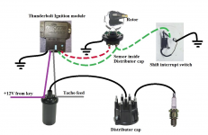
I posted a simplified drawing of how all the components of a Thunderbolt ignition system are connected. I host my drawings and picture on my ISP servers (started doing that after Photobucket decided to hold the world to ransom :mad:), and for some stupid reason, some ISPs in the good ol' US of A think my ISP is a spam site, and block the links. So sort out your ISP and get them to unblock iiNet.

Chris.....
 

nola mike

Vice Admiral
Joined
Apr 22, 2009
Messages
5,364
The original ignition sensors had a couple of screw terminals, and that's where the white/red and the white/green connected. It was even written on the sensor which terminal was which. By the sound of it, and a photo or 3 would be really helpful here, at some stage the sensor has been replaced and the new one is of the new style, with flying leads, not screw terminals. IF the upgrade was done as per Merc's instruction, somewhere along the leads (both the white/red and the white/green) between the sensor and the ignition module will be a connection with a couple of ring terminals held together with a screw and a sleeve of adhesive lined heatshrink over them. This is where you break into the white/green and add the white/green from the interrupt switch.

My understanding of his situation was that everything was working at one point, OP disconnected the wires, and is now trying to put it back together. Which means there should be an existing place for the wht/grn wires to screw together.

Also, you think it would fry the ignition rather than just kill spark? Doesn't the module just provide a switched ground to the coil neg? (I'm not going to try it either though)
 

achris

More fish than mountain goat
Joined
May 19, 2004
Messages
27,468
...Also, you think it would fry the ignition rather than just kill spark? Doesn't the module just provide a switched ground to the coil neg? (I'm not going to try it either though)
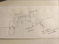
Thinking about it, I think you may be right... I once designed a replacement for the TB-IV module, as Merc NLA'd it and the replacement TB-V module is an eye-watering $500 plus. My design has about $30 in parts, but the output stage looks like this.....
1619040451215.png
But, I know there's also some circuitry in the module that monitors current through the coil while it's charging, and grounding the coil negative will send the current up, probably beyond design expectations, so the results could be as mild as, nothing, or as bad as, 'please replace the ignition module'... Is anyone willing to contribute to the knowledge base of the planet and try this and let us know what happens? Thank you for your service, in advance. :)
 

Rivergator

Petty Officer 1st Class
Joined
May 7, 2013
Messages
224
achris, I just came across one of your postings from 6-24-2016 "Mercruiser Thunderbolt Ignition Systems" which is really illuminating and helpful. Especially intriguing was one sentence "For troubleshooting I always remove the tacho feed wire and the white/green to the shift interrupt switch, eliminating them as a possible cause of a problem" The tach feed wire is on the minus pole of the coil and it didn't say where the white/green wire was but I was thinking if they create the same symptoms or interference with your testing procedure, maybe they are in the same circuit, ??? ---- I don't know, just thinking out loud. But I think we are getting closer to solving this problem and in the end we may just end up on the minus pole of the coil, but I too don't want to test it and blow my ignition system.
Nola, you are right. I am just putting everything back they way I took it apart. I didn't change anything. I can kill myself now not taking a clear picture of the coil. I hope you have an answer after looking at your boat.
 

achris

More fish than mountain goat
Joined
May 19, 2004
Messages
27,468
achris, I just came across one of your postings from 6-24-2016 "Mercruiser Thunderbolt Ignition Systems" ...
Then you see that the interrupt switch white/green is connected to the sensor, NOT the coil. DO NOT connect it to the coil. That would have it see in excess of 400v across it. They are designed for no more than 120v...
Especially intriguing was one sentence "For troubleshooting I always remove the tacho feed wire and the white/green to the shift interrupt switch, eliminating them as a possible cause of a problem" The tach feed wire is on the minus pole of the coil and it didn't say where the white/green wire was but I was thinking if they create the same symptoms or interference with your testing procedure, maybe they are in the same circuit, ??? ----
No, the gray wire for the tacho is on the coil negative. The interrupt switch white/green is on the sensor. They will both cause no spark if faulty, but for very different reasons.
..But I think we are getting closer to solving this problem and in the end we may just end up on the minus pole of the coil, ...

Last time I'm going to say it. DO NOT put the interrupt switch wire (white/green) on the coil negative. That is NOT where is goes. LOOK AT MY DIAGRAM! the interrupt switch white/green goes with the white/green that runs between the module and the sensor. If you can't find a post for it to connect to, just splice (and solder!) it into the white/green.

Chris......
 

Rivergator

Petty Officer 1st Class
Joined
May 7, 2013
Messages
224
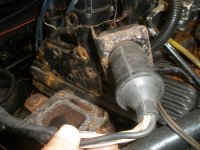
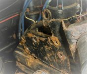
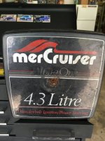
Ok, here it is. I finally found a picture of my engine before I took it out of the boat on my old camera rather than my iphone and thank God it actually shows the coil. Unbelievable, what luck. But that doesn't make me feel any more confident, because there is always Murphy's Law and I will heed Chris' advise unless he says otherwise. He seems to know a lot about this ignition stuff. Ok, the white/green wire clearly hooks up to the (-) side of the coil (I can tell because I can see a purple wire on the other side and we know purple goes to (+) (see pictures). It looks like that this has been for a long time if not forever and I don't think anybody every messed with this. I also doubt that somebody upgraded at one point in time from a breaker point ignition to a TB IV, because only a totally anal geek would also put in the effort to replace the carburetor breather with a corrected one showing it to be a TB ignition (see picture), but then again it could be possible, because of the type of old coil (I get to that later). It s also possible that somebody upgraded the distributor sensor from an old style (2 mounting nuts and the ground wire attached to one of the sensor mounting screws) to the new style (like I have, 3 wires, hardwired to the sensor). That could explain the ring connector on the white/green wire coming from the shift interrupt switch, which could have been attached to one of the nuts of the old style sensor on the distributor and was subsequently moved to the (-) pole of the coil after the sensor was upgraded to the new style which no longer made it possible to connect the white/green wire to the distributor.....or was it all done originally by Mercruiser and the boat was delivered that way? Who knows? However, everything is the same as it was when I took it apart, EXCEPT for one thing and that may be critical. I threw out the old coil and replaced it with a new one, because the old one was badly rusted on the bottom and I thought it might be wise to just replace it. I made sure that the new coil was TB compatible and when I compared it to the old one, I noticed that the old coil had written on the outside USE WITH EXTERNAL RESISTOR and the new coil has nothing written on it. What does it all mean? All you thinkers out there, what shall I do?
 

Attachments

  • P5290073O (1).jpg
    P5290073O (1).jpg
    138 KB · Views: 14
  • P5290073.jpg
    P5290073.jpg
    476.3 KB · Views: 15
  • IMG_0698 (1).jpg
    IMG_0698 (1).jpg
    136.8 KB · Views: 15

alldodge

Moderator
Staff member
Joined
Mar 8, 2009
Messages
42,064
Help for Old Folks
Breaking up your sentences makes it much easier for old guys like me to read on the computer. Not doing a Ms, Gramer, just making it easier to follow

The TB uses a coil with internal resistor
Coils marked "use external resistor" are for points ignition

Is it possible that the sensor was upgraded from 2 wire to 3 wire TB sensor, sure. All new sensors are 3 wire

It sounds like the wiring is correct and matches Chris post 20
 

nola mike

Vice Admiral
Joined
Apr 22, 2009
Messages
5,364
Help for Old Folks
Breaking up your sentences makes it much easier for old guys like me to read on the computer. Not doing a Ms, Gramer, just making it easier to follow

The TB uses a coil with internal resistor
Coils marked "use external resistor" are for points ignition

Is it possible that the sensor was upgraded from 2 wire to 3 wire TB sensor, sure. All new sensors are 3 wire

It sounds like the wiring is correct and matches Chris post 20
I still can't see chris's post, but I can't find a scenario where the grn/wht connects to the coil unless it's a points ignition. Which it may have been at one point given his coil. OP, you really need to trace your wires completely. Who knows what's going on there. Find out what's happening at the terminal block. Again, trace the wires from the interrupt switch back. If the grn/wht connects to your coil, where does the gray from your ign amp go?
 

Rivergator

Petty Officer 1st Class
Joined
May 7, 2013
Messages
224
The TB uses a coil with internal resistor
Coils marked "use external resistor" are for points ignition.
Maybe, maybe NOT. This is crazy and I will get to the bottom of this issue. I looked at the Sierra 18-5438 coil and it says the following to describe the coil: Fits GM V-6 and V-8 engines with HEI Thunderbolt IV and V ignitions. Printed on the coil itself it says: USE OF EXTERNAL RESISTOR REQUIRED underneath that is a label glued to the coil which says: if used on NON-Thunderbolt ignitions. That indicates that the coil is backward compatible and can be used on both type ignitions. For all I know my old coil most likely was like that and the white/green wire is still on the (-) pole of the coil. It is possible that some wise guy made a big mistake putting it there at some point in time but by the looks of the coil we all can agree that it must have been like this for ages and I assume the boat was running like that.
Is it possible that the sensor was upgraded from 2 wire to 3 wire TB sensor, sure. All new sensors are 3 wire
Yes it is possible and most likely did happen. They went from old style to new style. I looked up the part Sierra 18-5116-1 which is the sensor and this part is no different than the old style, except that it no longer has screws to attach any wire to and the ground wire is no longer screwed to the bottom of the distributor, but is hardwired along with the other 2 wires. Isn't it strange that this replacement part which replaces an official Mercruiser OEM part HAS NO CONNECTION for a white/green shift interrupt wire when every outdrive has one of these and it is an essential and absolutely necessary function. And who would design a mediocre part like this where the customer is expected to do a cheesy splice job to accommodate this wire. I also looked at all the reviews of all the people who bought this Sierra 18-5116-1 sensor and nobody expressed any problems installing it or even mentioned this white/green wire once. Could it be that this wire never came into the picture because it was always wired to the (-) side of the coil and never was an issue????????
It sounds like the wiring is correct and matches Chris post 20
I never saw Chris' #20 post. it is blank. I wish I knew what it was, but I don't.
 

Rivergator

Petty Officer 1st Class
Joined
May 7, 2013
Messages
224
I still can't see chris's post, but I can't find a scenario where the grn/wht connects to the coil unless it's a points ignition. Which it may have been at one point given his coil. OP, you really need to trace your wires completely. Who knows what's going on there. Find out what's happening at the terminal block. Again, trace the wires from the interrupt switch back. If the grn/wht connects to your coil, where does the gray from your ign amp go?
Everybody talks about the terminal block but has yet to tell me where it is. The grey wire from the ignition amp goes to the (-) coil, so does another grey wire from the harness. The purple wire from the ignition amp goes to the (+) coil, so does another purple wire from the harness. A white/green wire and a white/red wire goes from the ignition amp to the same colored wires on the distributor. And that's it. All other wires from the harness are in their rightful places and connected. I will double check all connections and check off against my wiring diagram, then I will test everything for continuity against the main connector plug.
 
Last edited:

Rivergator

Petty Officer 1st Class
Joined
May 7, 2013
Messages
224
I don't get it. Of all the boaters in the country who surf the iboats forum there must be 100s that have a 1988 or 89 boat with a 4.3 engine with TB IV ignition and a new style distributor (3 molded in place wires). If you do, would you please take a look at your boat and see where the white/green wire is that comes from your shift interrupter switch on your shift plate. I really would be grateful.
 

achris

More fish than mountain goat
Joined
May 19, 2004
Messages
27,468
Here's the image from my post that you all can't see (no idea why)...
1619396567698.png
The terminal block referred to is on the shift plate, and has a screw that holds it to the plate, which the black wire from the interrupt switch goes to (which is ground because of the connection to the plate), and another screw that has 2 white/green wires. One to the switch, the other to the ignition module or sensor.

1619396892207.png
 

achris

More fish than mountain goat
Joined
May 19, 2004
Messages
27,468
Everybody talks about the terminal block but has yet to tell me where it is.
On the shift plate.
The grey wire from the ignition amp goes to the (-) coil, so does another grey wire from the harness.
The gray from the amp 'grounds' (internally, sort of) to fire the coil. The other gray wire is the tacho feed.
The purple wire from the ignition amp goes to the (+) coil, so does another purple wire from the harness.
The purple from the harness is your 'switched power'. It supplies 12v to the amp, via the coil +.
A white/green wire and a white/red wire goes from the ignition amp to the same colored wires on the distributor.
These are the supply (white/red) and trigger (white/green) for the sensor.

You need to spline the white/green from the interrupt switch into the white/green that runs between the amp and the sensor.

Can you post a photo of the amp and distributor in the one shot? Have you run your fingers along the white/green between amp and distributor? Is there a join in it somewhere? If so, this is where you can join the white/green from the interrupt switch in.

Chris.....
 

nola mike

Vice Admiral
Joined
Apr 22, 2009
Messages
5,364
On the shift plate.

The gray from the amp 'grounds' (internally, sort of) to fire the coil. The other gray wire is the tacho feed.

The purple from the harness is your 'switched power'. It supplies 12v to the amp, via the coil +.

These are the supply (white/red) and trigger (white/green) for the sensor.

You need to spline the white/green from the interrupt switch into the white/green that runs between the amp and the sensor.

Can you post a photo of the amp and distributor in the one shot? Have you run your fingers along the white/green between amp and distributor? Is there a join in it somewhere? If so, this is where you can join the white/green from the interrupt switch in.

Chris.....
So thinking about this more, looks like he did have that grn/wht on the coil. So if grounding green through the coil didn't fry anything, it should function properly, right?
 

achris

More fish than mountain goat
Joined
May 19, 2004
Messages
27,468
So thinking about this more, looks like he did have that grn/wht on the coil. So if grounding green through the coil didn't fry anything, it should function properly, right?
Maybe, but you would be subjecting the interrupt switch to over 400v, and it's only rated to 120v... Eventually you'll draw an arc (internally) that will burn it out... The TB systems don't have an arc suppressing capacitor (condenser) like the old points systems.
 

nola mike

Vice Admiral
Joined
Apr 22, 2009
Messages
5,364
Maybe, but you would be subjecting the interrupt switch to over 400v, and it's only rated to 120v... Eventually you'll draw an arc (internally) that will burn it out... The TB systems don't have an arc suppressing capacitor (condenser) like the old points systems.
How significant is that 400v? It doesn't hurt the tach, right? Or the gray wire on the ign amp? I think it's conceivable that he was wired that way without issue.
 

achris

More fish than mountain goat
Joined
May 19, 2004
Messages
27,468
How significant is that 400v? It doesn't hurt the tach, right? Or the gray wire on the ign amp? I think it's conceivable that he was wired that way without issue.
You might do it, he might do, I wouldn't....
 

achris

More fish than mountain goat
Joined
May 19, 2004
Messages
27,468
How significant is that 400v?
Tell you what. Stick your fingers in a 3 phase socket, then tell me how significant that voltage is (and that's 'only' 220v BTW)....

It's the voltage that creates arcs, and 400v arcing across contacts designed for 120v is going to eventually lead to burning, and failure. That's isn't an hypothesis, it's a fact.

But I'm also just as sure that the OP will do what he thinks is ok, regardless of evidence to the contrary... And as long as that's not on my boat, so be it.

I'm out,

Chris....
 
Top