Overhauling my 1988 Alpha One Drive Train

Rivergator

Petty Officer 1st Class
Joined
May 7, 2013
Messages
224
............continued from "Overhauling my 1988 Mercruiser 4.3 ltr engine"

I am about to start cleaning up and restoring the bilge of my 1988 Sylvan bow rider and going over the transom assembly I started with a thorough clean up of the inside of bellows, bell housing, gimbal housing, inner transom plate and removal of the Y pipe. I was hoping that I could do this without further dismantling the transom, but I realize that I will not be that lucky. From what I can see so far there is noticeable corrosion on the areas where the u-j bellow attaches, so it is necessary for me to remove the bell housing to get a closer look. My hinge pin tool is on order (I understand removing the hinge pins could be a real bear) but for right now what is very confusing to me is the removal of the shift cable. I do have the Mercruiser Service Manual #6 but still! From what I can gather my shift cable is the new style, it has the lock nut on the rear end of the bell housing. My big question is, what needs to be done to the shift cable in order to remove the bell housing? The shift cable seems to be in good order and I want to use it again when putting the bell housing back. Can I do that or will the shift cable have to be destroyed in order to remove the bell housing? Is the tool 91-12037 necessary to remove the shift cable and how is this tool to be used. No instructions or YouTube to be found anywhere. I sure need your help with this new task, thanks!
 

alldodge

Moderator
Staff member
Joined
Mar 8, 2009
Messages
42,064
The cable can be removed with the bell housing after the cable is removed from the jacket, or remove the cable and then with a deep well socket the nut. Either way, need to remove the cable before the bell housing can be removed.

Now if you want to just move the bell housing out of the way, then just leave the shift cable connected.

To remove bell away from transom. Disconnect center cable at the shift plate by loosening the anchor screws on each side. Remove plastic end guide from cable, then remove brass support tube from jacket. Go to Bell and remove set screw from shift slide and pull cable and shift slide out.

Now loosen nut on end of shift cable jacket and the Bell can be removed

See pages 4A-14 thru 4A-16 in manual 6
 

achris

More fish than mountain goat
Joined
May 19, 2004
Messages
27,468
While you're this deep, check the upper steering pin and steering arm for wear. Quite common on the earlier A1s.
 

Rick Stephens

Admiral
Joined
Aug 13, 2013
Messages
6,118
I would be inclined to replace the shift cable while you are in there. Shift cables are a wear item and need periodic replacement anyway.
 

Rivergator

Petty Officer 1st Class
Joined
May 7, 2013
Messages
224
Please forgive me if I have no clue or conception of how the lower cable actually works, since I am totally new to the Alpha One world. Engines are a bit more generic and I am familiar with most aspects of that technology. Also I am pretty engineering savvy and usually have no problem understanding how things work. Even though I have the Mercruiser Manual I still was totally in the dark about which end goes where and what is up and what is down, until I came across a couple of great YouTube clips showing step by step how it all works. Now I have a much better idea but still have some questions. On the Service Manual section 4B page 7 paragraph 6/c, it says cut core wire if needed. WHY? Also (correct me if I am wrong) my understanding is, alldoge, if I disconnect the lower shift cable from the shift plate (inside the boat), remove the clamp on the smaller end of the shift cable bellow I should then be able to pull the bell housing away from the gimbal ring for approximately the length of the cable that is inside the boat. Also please confirm; removing just the core wire still will not allow me to remove the cable conduit because it is the new style which screws in from behind the gimbal housing and not in front of it (like the old style)j. I assume this is not just a retaining nut, right? And btw. forget about tool 91-12037, there are less expensive and better solutions available.
 
Last edited:

Rivergator

Petty Officer 1st Class
Joined
May 7, 2013
Messages
224
Also when I removed the Y pipe at first I thought there was a bolt missing, Then I realized that one of the holes don't line up. Somebody goofed, I guess. As I am preparing for the worst (corrosion beyond repair in both bell and gimbal housings) and I was looking on ebay to see what is coming at me I saw some gimbal housings with 5 holes, 3 on top of which 2 will line up with the Y pipe and some with 4 holes (1 off to the side) like mine and I thought I even saw one with only 4 holes but all 4 are correct and line up with the Y pipe. What is the significance of that? If I wind up replacing the transom assembly could I get the one where the holes line up correctly or will it interfere with existing components like my alpha one drive etc. ??
 

alldodge

Moderator
Staff member
Joined
Mar 8, 2009
Messages
42,064
First New style has nut on front of the Bell, and old has the nut on the rear of the Bell. With your nut being on the rear then you have old style.

if I disconnect the lower shift cable from the shift plate (inside the boat), remove the clamp on the smaller end of the shift cable bellow I should then be able to pull the bell housing away from the gimbal ring for approximately the length of the cable that is inside the boat

Yes, but there is a BUT
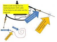
The entire cable (core and jacket) will come out, but you need to have a string attached to the outer jacket to get it back in the boat. The jacket being stiff will go into the bell housing on the motor because it doesn't bend very well. A string is attached to the core jacket so it can be pulled back in where it needs to go

Bravo cable string tool.jpg

The issue you run into is the string tool is made from a piece of the old cable. You may still get it done but need to figure out how to attached.

You could get a new style cable and tap the threads into the Bell. Just noticed the motor is out

Also please confirm; removing just the core wire still will not allow me to remove the cable conduit because it is the new style which screws in from behind the gimbal housing and not in front of it (like the old style)

The nut behind or in front is the same, cable can come out.

The exhaust is probably because you have a new style Y pipe (4 bolts in a square pattern) and old transom assembly used 5 holes
 

Rivergator

Petty Officer 1st Class
Joined
May 7, 2013
Messages
224
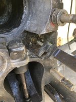
Thanks alldodge, I am clear now on the shift cable. I am going to pull it out and will put it back because it is in excellent shape as a teaching experience. I learn best by doing it. Btw. should these cables be lubed as part of maintenance or is it better not to. Also I think we mix up the 'in front and behind' of the gimbal housing. I am was standing behind the boat facing the front and I meant "before" to be between the transom and the bell housing and behind is the very end of the bell where it attaches to the drive. According to the Service Manual I read it as having the new style cable (see picture). If this is the old style please correct me. Also can anybody please go into more detail and shed some light on my question in post #6. What is it with the inconsistency of the hole pattern in the gimbal and the Y pipe. Thanks!
 

Attachments

  • IMG_0669 (1).jpg
    IMG_0669 (1).jpg
    159.3 KB · Views: 21

alldodge

Moderator
Staff member
Joined
Mar 8, 2009
Messages
42,064
Agree, we're getting mixed on the front and rear
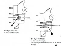
You have old style where the cable is screwed into the bell housing. To install a new style, the threaded hole is drilled out, new cable slides in, and nut goes on the outside at the cable end. Makes it much easier to change
Alpha cable old and new.jpg

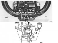
The transom assembly exhaust port changed in newer years. The old is on top and new on bottom

exhaust.jpg
 

Bt Doctur

Supreme Mariner
Joined
Aug 29, 2004
Messages
19,292
alldodge, he has a alpha not a bravo ,
the threaded hole is drilled out, new cable slides in, and nut goes on the outside at the cable end.
 

alldodge

Moderator
Staff member
Joined
Mar 8, 2009
Messages
42,064
alldodge, he has a alpha not a bravo ,
the threaded hole is drilled out, new cable slides in, and nut goes on the outside at the cable end.
Agree, but I'm not seeing the nut in the pic above. My pic of the Bell above came from Manual 6

My eyes are not seeing to good some time so maybe I'm missing it
 

Rivergator

Petty Officer 1st Class
Joined
May 7, 2013
Messages
224
When I removed the wiring harness, I labeled everything carefully just to make sure that everything goes back the way it came apart, but unfortunately some of the labels got soiled badly to the point where I have a hard time reading them. Most of them I was able to recognize but there is one that has me stunned. It is the white/green wire that comes from the shift cut out switch and like I said the label is very difficult to make out but I could swear it says (-) coil. Now when I look at the wiring diagram for my 1988 4.3 ltr engine, it says that that wire is supposed to go to the distributor. Is it possible that this wire could go either way, was it wired incorrectly (which is doubtful) or could I have labeled it incorrectly (which I also doubt). Help!
 

alldodge

Moderator
Staff member
Joined
Mar 8, 2009
Messages
42,064
Being a 1988 it should be points. I'm seeing the white/green could go to the Neg side of the coil and also goes to the shift interrupter

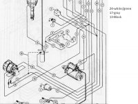
Pic is from Manual 7 and my guess is the 17 (gray wire) in fact would be 24 (white/green)


1988 V6.jpg
 

Rivergator

Petty Officer 1st Class
Joined
May 7, 2013
Messages
224
No, it's actually a T-bolt IV with the ignition module mounted to the port header knee, the pointless distributor and a proud sign on the carburetor breather cap
 

alldodge

Moderator
Staff member
Joined
Mar 8, 2009
Messages
42,064
Is always best to know what were working on

The TB4 and TB5 have the white/green coming from the distributor and connecting to the shift interrupter for the Alpha drive
 

nola mike

Vice Admiral
Joined
Apr 22, 2009
Messages
5,364
Thanks alldodge, I am clear now on the shift cable. I am going to pull it out and will put it back because it is in excellent shape as a teaching experience. I learn best by doing it. Btw. should these cables be lubed as part of maintenance or is it better not to. Also I think we mix up the 'in front and behind' of the gimbal housing. I am was standing behind the boat facing the front and I meant "before" to be between the transom and the bell housing and behind is the very end of the bell where it attaches to the drive. According to the Service Manual I read it as having the new style cable (see picture). If this is the old style please correct me. Also can anybody please go into more detail and shed some light on my question in post #6. What is it with the inconsistency of the hole pattern in the gimbal and the Y pipe. Thanks!
I ran into the same issue. Apparently there were 2 different styles of transom plate, one of which doesn't line up with your y pipe. Merc mixed both of them for a while, so they thought it was ok to run with only 3 bolts. A few guys on here did as well with no problems. I also did it.
 

Rivergator

Petty Officer 1st Class
Joined
May 7, 2013
Messages
224
Is always best to know what were working on

The TB4 and TB5 have the white/green coming from the distributor and connecting to the shift interrupter for the Alpha drive
On mine the white/red and white/green wires are coming from the TB IV ignition amplifier and go the distributor, then there is a purple and grey wire coming from the ignition amplifier and going respectively to the + and - poles on the coil. Then there is one more wire coming from the ignition amplifier which is black and ground. More detail with pictures in my next post
 

Rivergator

Petty Officer 1st Class
Joined
May 7, 2013
Messages
224
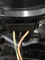
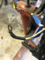
I am still utterly confused about this one wire. I am going to be specific so we are all on the same page. This is from Service Manual #7
1) page 4E-1 - V6 engine (earlier models) wiring with starter motor fuse. I don't think I have that motor. If I am not mistaken this has a breaker point ignition. Mine is a TB IV.
2) page 4E-2 - V6 engine (earlier models) wiring w/o starter motor fuse. Again, I don't think that applies to me for the same reason as above. But if I am wrong please correct me.
3) page 4E-3 - V6/V8 - pre - 1989 models. Now that looks like what I have, same ignition amplifier, the wires that come out of it are the same but when I look at the distributor mine is different than the picture on the diagram. There are 3 wires coming out of it and they are hard wired into the sensing unit and I am not able to attach the white/green wire coming from the shift interrupter switch there. The connector on the white/green wire is such that it was most likely connected to a screw like the screw on the (+) or (-) pole on the coil. Like I mentioned before I suspect that it was connected there but now I am totally confused and not sure. I don't want to make a mistake and then blow something out. The diagram shows a grey wire coming from shift interrupter switch going to a connector block (where is that connector block) and then it changes and a white/green wire coming out of the connector block going to the distributor (except in my case. My distributor does not have screws to connect things to). Has anybody ever seen anything like this before? Will the white/green wire go on the (+) or (-) poles of the coil. Obviously it hasn't been going to the coil like the diagram says. Where would it go???
4) page 4E-4 - V6/V8 - 1989 models - ON That diagram is not the right one either, because the ignition amplifier dosn't look like mine. So I guess 3) is the correct diagram.
 

Attachments

  • IMG_0690.JPG
    IMG_0690.JPG
    1.5 MB · Views: 11
  • IMG_0692.JPG
    IMG_0692.JPG
    1.4 MB · Views: 12

nola mike

Vice Admiral
Joined
Apr 22, 2009
Messages
5,364
The why/grn wire from your distributor goes directly to the terminal block and screws on there. Follow the gray wire from the shift interrupt switch back. The terminal block is pretty close iirc.

Edit: oh, I see your issue. The grn/wht should connect to the other grn/wht, doesn't matter how. Will they both reach the terminal block?
 
Last edited:

achris

More fish than mountain goat
Joined
May 19, 2004
Messages
27,468
Thunderbolt.jpg
 
Top