No Power to Helm ---- How To Test Voltage

Status
Not open for further replies.

Don S

Honorary Moderator Emeritus
Joined
Aug 31, 2004
Messages
62,321
This is just a basic tutorial on how to use a Digital Multi Meter (DMM) to test voltage and ground to the boats fuse panel at the helm, and a little bit of other information at the end. It's not a end all tutorial, just a quick how to so you can get back on the water as soon as possible. You will probably find a need to get a book on marine electrical to really start understanding it, but with luck, this will get you back on the water until then.

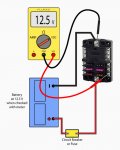
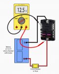
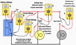
Typically, you have a Positive and negative wire running from the battery to the helm fuse panel. In the diagrams following the panel has a negative buss bar built in at the top, and the lower section is for the positive 12V distribution.
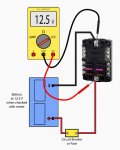
There should also be a fuse or circuit breaker near the battery to protect the wiring going to the helm.

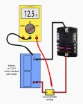
The first thing you must check is your battery voltage. Start by turning your DMM to Volts DC. Your meter will be different than the one shown, so look at the instructions that came with your particular meter.

The black test lead always goes in the Common terminal of the DMM, and the Red lead will go in the V/Ω terminal of the meter.

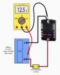
Touch the test leads to the battery terminals, not the cable, cable ends or the attaching nut. This will give you’re your battery voltage reading that you will compare all your other tests from. In the examples, I am using 12.5 v. Then touch the cable ends, the cable itself if open, and the attaching battery connectors to make sure you still have the same voltage.
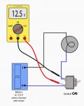
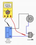
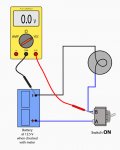
attachment.php
 

Attachments

  • Batt check.jpg
    Batt check.jpg
    105.5 KB · Views: 21

Don S

Honorary Moderator Emeritus
Joined
Aug 31, 2004
Messages
62,321
Continued

Continued

Next step is to Verify that you have voltage going into the fuse or circuit breaker and coming out of it. Many times a fuse can look good, but it's not making good electrical contact or the fuse is blown but actually looks ok. This is why you should check both the input and the output side of the fuse/circuit breaker.

Note the black test lead is always on a good ground for doing these tests. Also note that the voltage stays at or very close to the battery voltage test you did earlier. Had it been a lot lower would have indicated a problem in the wiring or the the fuse/circuit breaker itself.

attachment.php
 

Attachments

  • V out of CB.jpg
    V out of CB.jpg
    113.4 KB · Views: 17

Don S

Honorary Moderator Emeritus
Joined
Aug 31, 2004
Messages
62,321
Continued

Continued

The next test will verify that the ground wire from the battery to the fuse panel is OK. You will need a long jumper wire for this. I have a 20' 10ga wire with alligator clips on each end that I find very useful in testing electrical systems.

Hook the jumper wire from the neg buss bar main terminal to the black test lead of the meter. Then touch the red test lead to the positive battery terminal. You should see at or near your battery voltage.

The picture below does not show the long jumper wire. (So, I'm lazy).


attachment.php
 

Attachments

  • Grd tp panel.jpg
    Grd tp panel.jpg
    106.7 KB · Views: 17

Don S

Honorary Moderator Emeritus
Joined
Aug 31, 2004
Messages
62,321
Continued

Continued

The next test will be to check the panel itself and the positive wiring from the battery fuse/circuit breaker to the fuse panel.
Long jumper no longer needed, black lead on the ground buss bar main terminal, and the red lead on the main wire connection point on the fuse side of the panel. You should again see at or near battery voltage at these points.

attachment.php
 

Attachments

  • V-G on panel.jpg
    V-G on panel.jpg
    110.3 KB · Views: 9

Don S

Honorary Moderator Emeritus
Joined
Aug 31, 2004
Messages
62,321
Continued

Continued

From there, with the black test lead still on the ground terminal you can check the individual fuses to make sure they are not blown or making poor contact by checking as shown below. You can do this on all the fuses.
If they all show OK, with your red lead on the main positive of the fuse panel, check with your black test lead to the other ground (negative) terminals (Second picture). Again your meter should show at or near battery voltage.


attachment.php


attachment.php
 

Attachments

  • Voltage after fuse.jpg
    Voltage after fuse.jpg
    114.8 KB · Views: 13
  • Panel neg term.jpg
    Panel neg term.jpg
    109.6 KB · Views: 12

Don S

Honorary Moderator Emeritus
Joined
Aug 31, 2004
Messages
62,321
Something a little Different

Something a little Different

This is just about being able to understand what your meter reading is telling you.
Say you have a very simple circuit as shown in the picture below. You know you have voltage up to the switch, but your light won't light up. You check power to the switch and have voltage, and the light still won't light up ............. WHY??????

attachment.php


Well, believe it or not, if you check the switch like that and you have power to the switch, and the system is good after the switch. It means one thing. The switch is bad. If it was good, the meter would read 0.0v.

Yeah, I know, sounds backwards, but it's not. I could set here and use all the big words and examples to water falls until your head explodes, but I'm not going to. Get a book on marine electrical systems and have at it if you want to know why and really understand marine electrical systems. For this "How to" let's just say that we are sure the switch is bad when tested in this manner.

Same thing would happen with a fuse, or a circuit breaker. If you measure voltage across both terminals and come up with battery voltage, it's bad. If it shows 0, it's good.

One other little note. If you hook the red and black test leads up backwards, you will get a minus sign (-) in front of the voltage.

Here is the correct way of checking for voltage to and from the switch.

attachment.php


Notice the negative (Black) test lead is back on a known good ground and the red lead tests the voltage to the input terminal (A) of the switch.
If you move the red test lead only, (Not the black) to terminal B of the switch, you will now get 0.0v on your meter. Which tells you nothing is getting through the switch.

attachment.php


What does all this mean?

Keep the black test lead on a good ground and do your voltage tests at the different locations unless you fully understand what voltage drop tests mean. If you have problems, ask on the forums. But at least you know how to properly test for voltage with your meter.


Here is another image that shows some testing methods without a lot of explanation. Might help you understand might not. If your not sure, by all means ask.


attachment.php


.
 

Attachments

  • switch test.jpg
    switch test.jpg
    94.4 KB · Views: 20
  • Switch 2.jpg
    Switch 2.jpg
    94.4 KB · Views: 14
  • switch3.jpg
    switch3.jpg
    93.5 KB · Views: 17
  • Misc tests.jpg
    Misc tests.jpg
    100.5 KB · Views: 20
Status
Not open for further replies.
Top