Need help sorting out electrical demons

Joe Reeves

Supreme Mariner
Joined
Feb 24, 2002
Messages
13,262
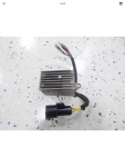
No doubt you have either a small 3 wire or 4 wire type rectifier, and if so, test it as follows.... However as you've already explained your testing... getting the same readings or no readings in both directions, yeah, that indicates a blown rectifier. Make absolutely sure of the voltages and polarity before you install a new one. Rectifiers will not tolerate reversed polarity even for a millisecond
********************
(Small Rectifier Test)
(J. Reeves)

Remove the rectifier wires from the terminal block. Using a ohm meter, connect the black lead of the ohm meter to the rectifier base (ground), then one by one, connect the red lead of the ohm meter to the yellow, yellow/gray, then the red wire (some rectifiers may also have a fourth yellow/blue wire. If so connect to that also). Now, reverse the ohm meter leads and check those same wires again. You should get a reading in one direction, and none at all in the other direction.

Now, connect the black lead of the ohm meter to the red wire. One by one, connect the red lead of the ohm meter to the yellow, yellow/gray, and if present, the yellow/blue wire. Then reverse the leads, checking the wires again. Once more, you should get a reading in one direction and none in the other.

Note that the reading obtained from the red rectifier wire will be lower then what is obtained from the other wires.

Any deviation from the "Reading", "No Reading" as above indicates a faulty rectifier. Note that a rectifier will not tolerate reverse polarity. Simply touching the battery with the cables in the reverse order or hooking up a battery charger backwards will blow the diodes in the rectifier assembly immediately.

********************
.
 

Mi_fiveo

Petty Officer 2nd Class
Joined
Jul 22, 2018
Messages
115
I followed your procedures and many of the readings showed the same in both directions. Guess I need a new rectifier. Between that and the new stator, I sure hope my problem will be fixed.
 

oldboat1

Fleet Admiral
Joined
Apr 3, 2002
Messages
9,612
regulator in that system? (thinking it was a regulator/rectifier in the 9.9).
 

Joe Reeves

Supreme Mariner
Joined
Feb 24, 2002
Messages
13,262
Water cooled Voltage regulator/rectifier on a 9.9hp??

If you have anything beyond a small 3 or 4 wire rectifier that looks round,about 1" in diameter, and also about 1" high... disregard my rectifier test instructions.

The water cooled regulator/rectifier assembly can NOT be tested with a ohm meter.

What kind of rectifier do you have on that engine?
 

Mi_fiveo

Petty Officer 2nd Class
Joined
Jul 22, 2018
Messages
115
This is what I have.
 

Attachments

  • photo297204.png
    photo297204.png
    1.1 MB · Views: 1

Mi_fiveo

Petty Officer 2nd Class
Joined
Jul 22, 2018
Messages
115
I think the non electric start model uses the smaller round regulator. Mine has the rectifier/regulator.
 

oldboat1

Fleet Admiral
Joined
Apr 3, 2002
Messages
9,612
Have a stator ordered. Could either go ahead and replace the reg./rectifier ($$), or hold off until the eBay stator arrives and see if your charging system works. Think I would keep the test brief if going that route.
 

Joe Reeves

Supreme Mariner
Joined
Feb 24, 2002
Messages
13,262
Having retired in 1991, my books only go up to 1992 and do not take in that square looking component. We need someone to jump in here with a guaranteed description of what that is.... rectifier only, regulator only, regulator/rectifier combo ??
 

Mi_fiveo

Petty Officer 2nd Class
Joined
Jul 22, 2018
Messages
115
I have the new stator. Haven’t tested yet. I did order a new rectifier/ regulator unfortunately.
 

Mi_fiveo

Petty Officer 2nd Class
Joined
Jul 22, 2018
Messages
115
The thing that confuses me is my old stator tested fine on the yellow wires ( which I think control the spark) and didn’t test ok on the brown wires. Which I think charge the battery. I have an internment spark issue and I’m it sure if that is the cause.
 

Joe Reeves

Supreme Mariner
Joined
Feb 24, 2002
Messages
13,262
The thing that confuses me is my old stator tested fine on the yellow wires ( which I think control the spark) and didn’t test ok on the brown wires. Which I think charge the battery. I have an internment spark issue and I’m it sure if that is the cause.

Just the opposite.... Yellow wires are for charging the battery..... Brown wires charge up the powerpack capacitor.
 

Steam

Cadet
Joined
Sep 27, 2017
Messages
26
I have seen exactly what you describe in your original post on aftermarket ignition switch installs done incorrectly.... albeit on heavy equipment, but same is same. No spark until you let off the start position could be as simple as the ignition circuit is connected to the accessory lead on the switch. The accessory circuit doesn't get power while the switch is in the crank position and then gets power when released to run position which would give you spark as you release to run. I would find the ignition wire and make sure it is on the ignition terminal of the switch. This would also explain why it can be pull started.
 

Mi_fiveo

Petty Officer 2nd Class
Joined
Jul 22, 2018
Messages
115
I checked every connection on the switch and verified which terminals are connected based on what position the switch is in. I also checked continuity between the switch and the end of the wiring harness and verified that each wire is connected to the correct location on the engine wiring harness. The switch is omc original and tested fine with a voltmeter. The weird thing is when I pull start it with the wiring harness disconnected, it runs but seems to be in a protected state and you can’t increase the throttle. Evinride has some fancy term for this, maybe S.LOW.

i though I was getting cross feed from the kill wire to the ground wire but this diagram shows that they are connected when the switch is in the off position. So I’m stumped. Either the stator is causing intermittent/weak spark or maybe my power coil is bad. I haven’t gotten that far yet. What a pain in the azz.
 

Attachments

  • photo297228.jpg
    photo297228.jpg
    69.9 KB · Views: 0

Joe Reeves

Supreme Mariner
Joined
Feb 24, 2002
Messages
13,262
********************
(Ignition Kill Circuit)
(J. Reeves)

A Black wire (ground) should lead from the powerhead to the powerpack. There will also be a Black/Yellow wire leading from the powerpack to a raised "M" terminal of the ignition switch. To complete the circuit, there will be a Black wire from the other "M" terminal of the ignition switch to ground.

When the key is in the OFF position = The two "M" terminals are connected,. effectively shorting/killing the ignition.

When the key in ON position = The two "M" terminals are not connected and the ignition is engaged.

********************
 

Joe Reeves

Supreme Mariner
Joined
Feb 24, 2002
Messages
13,262
I believe this motor is a 4 stroke with optical ignition.

Uh,oh.... I wonder! He said that the model number is E10El4EEB. That should be a 1999 9.9hp Evinrude but there is a "4" in that model number that I didn't give any thought to. If you are correct, I will back out of this discussion.
 
Top